|
전자부품 데이터시트 검색엔진 |
|
|
전자부품 데이터시트 검색엔진 |
|
ADP1613ARMZ-R7 데이터시트(PDF) 37 Page - Analog Devices |
|
|
|||||||||||||||||||||||||||||
ADP1613ARMZ-R7 데이터시트(HTML) 37 Page - Analog Devices |
|
|
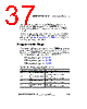
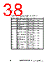
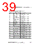
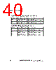
37 / 75 page  ADSP-BF506F EZ-KIT Lite Evaluation System Manual 2-3 ADSP-BF506F EZ-KIT Lite Hardware Reference is configurable over the 2-wire interface (TWI) signals. Refer to the power-on-self test (POST) example in the ADSP-BF506F installation directory of VisualDSP++ for information on how to set up the TWI interface. The core voltage and clock rate can be set up on the fly by the processor. The input clock is 25 MHz. The default boot mode for the processor is SPI flash boot. See “Boot Mode Select Switch (SW2)” for information on how to change the default boot mode. Programmable Flags The processor has 35 general-purpose input/output (GPIO) signals spread across three ports (PF, PG, and PH). The pins are multi-functional and depend on the ADSP-BF506F processor setup. The following tables show how the programmable flag pins are used on the EZ-KIT Lite. • PF programmable flag pins – Table 2-1 PG programmable flag pins – Table 2-2 PH programmable flag pins – Table 2-3 Table 2-1. Port F Programmable Flag Connections Processor Pin Other Processor Function EZ-KIT Lite Function PF0 TSCLK0/UA0_RX_ALT/TMR6/ CUD0 Default: LED0 Land grid array, expansion interface II PF1 RSCLK0/UA0_TX_ALT/TMR5/ CDG0 Default: LED1 Land grid array, expansion interface II PF2 DT0PRI/PWM0_BH/PPI_D8/ CZM0 Default: LED2 Land grid array, expansion interface II PF3 TFS0/PWM0_BL/PPI_D9/ CDG0 Default: PB0 Land grid array, expansion interface II |
|
링크 URL |
| ALLDATASHEET 가 귀하에 도움이 되셨나요? [ DONATE ] |
Alldatasheet는? | 광고문의 | 운영자에게 연락하기 | 개인정보취급방침 | 링크 투 데이터시트 | 링크교환 | 제조사별 검색 All Rights Reserved©Alldatasheet.com |
| Russian : Alldatasheetru.com | Korean : Alldatasheet.co.kr | Spanish : Alldatasheet.es | French : Alldatasheet.fr | Italian : Alldatasheetit.com Portuguese : Alldatasheetpt.com | Polish : Alldatasheet.pl | Vietnamese : Alldatasheet.vn Indian : Alldatasheet.in | Mexican : Alldatasheet.com.mx | British : Alldatasheet.co.uk | New Zealand : Alldatasheet.co.nz |
|
Family Site : ic2ic.com |
icmetro.com |
 Korean ▼
 English
 Chinese
 German
 Japanese
 Russian
 Korean
 Spanish
 French
 Italian
 Portuguese
 Polish
 Vietnamese
 Indian
 Mexican
 British
 New Zealand