|
전자부품 데이터시트 검색엔진 |
|
|
전자부품 데이터시트 검색엔진 |
|
ADP1613ARMZ-R7 데이터시트(PDF) 49 Page - Analog Devices |
|
|
|||||||||||||||||||||||||||||
ADP1613ARMZ-R7 데이터시트(HTML) 49 Page - Analog Devices |
|
|
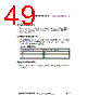
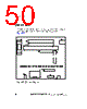
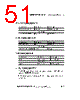
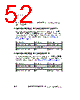
49 / 75 page  ADSP-BF506F EZ-KIT Lite Evaluation System Manual 2-15 ADSP-BF506F EZ-KIT Lite Hardware Reference Reset LED (LED1) When LED1 is lit, it indicates that the master reset of all the major ICs is active. The reset signal is controlled by the Analog Devices ADM708 supervisory reset circuit. GPIO LEDs (LED2–4) Three LEDs connect to the three general-purpose I/O pins of the proces- sor (see Table 2-6). The LEDs are active high and lit by writing a “1” to the correct programmable flag signal. Power LED (LED5) When LED5 is lit solid, it indicates that power is being properly supplied to the board. Table 2-6. GPIO LEDs LED Reference Designator Processor Programmable Flag Pin LED2 PF0 LED3 PF1 LED4 PF2 |
|
링크 URL |
| ALLDATASHEET 가 귀하에 도움이 되셨나요? [ DONATE ] |
Alldatasheet는? | 광고문의 | 운영자에게 연락하기 | 개인정보취급방침 | 링크 투 데이터시트 | 링크교환 | 제조사별 검색 All Rights Reserved©Alldatasheet.com |
| Russian : Alldatasheetru.com | Korean : Alldatasheet.co.kr | Spanish : Alldatasheet.es | French : Alldatasheet.fr | Italian : Alldatasheetit.com Portuguese : Alldatasheetpt.com | Polish : Alldatasheet.pl | Vietnamese : Alldatasheet.vn Indian : Alldatasheet.in | Mexican : Alldatasheet.com.mx | British : Alldatasheet.co.uk | New Zealand : Alldatasheet.co.nz |
|
Family Site : ic2ic.com |
icmetro.com |
 Korean ▼
 English
 Chinese
 German
 Japanese
 Russian
 Korean
 Spanish
 French
 Italian
 Portuguese
 Polish
 Vietnamese
 Indian
 Mexican
 British
 New Zealand