|
전자부품 데이터시트 검색엔진 |
|
|
전자부품 데이터시트 검색엔진 |
|
AS3931 데이터시트(PDF) 25 Page - ams AG |
|
|
|||||||||||||||||||||||||||||
AS3931 데이터시트(HTML) 25 Page - ams AG |
|
|
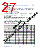
25 / 31 page  www.austriamicrosystems.com/AS3931 Revision 6.2 24 - 30 AS3931 Datasheet - Extende d O peratio n 10 Extended Operation 10.1 Power Management 10.1.1 Sleep Mode In sleep mode, all channels are switched off, taking no current except for the bias cells of the amplifiers. Sleep mode is entered by register setting, bits P0, P1, P2 set to 0. The remaining elements that take current are the oscillator and the regulator (if used). The Serial Programming Interface remains active also in the sleep mode. 10.1.2 Standby Mode In standby mode, selected channels are switched on, ready to receive data. The amplifier of the selected channel is on, whereas the correlator is powered down as long as no input signal is detected at the input. Enabling the related channel when setting bits P0, P1 or P3 enters the standby mode. In the standby mode, the current consumption increases by the amplifier currents compared to the sleep mode. 10.1.3 Receive Mode An enabled channel automatically changes from the standby mode to the receive mode as soon as an input signal is detected. The channel stays in receive mode as long as an input signal is detected. In receive mode, the correlator of the channel is active, scanning the input signal waveform for a valid wake up pattern. The channel goes back to standby mode if no input signal is detected for more then a fixed timeout period. The timeout period is approximately 3.3 ms. by this operating principle it is guaranteed, that the correlators are only active and taking current as long as it is really necessary. 10.1.4 Regulator On/Off The regulator can be switched off to reduce the current consumption. When switching off, the supply voltage is bypassed unregulated to the internal circuits, so VREG = VCC. Otherwise, the internal voltage is regulated to 2.4 V. Switching off the regulator saves about 1 µA of current. The regulator should only be switched off, when VCC is not higher then 3.3 V, otherwise the current consumption is increased because the internal circuits will then take more current. 10.1.5 Typical Current Consumption in Different Modes The Table 28 gives an overview of the typical current consumptions in the different modes. All three channels are used in this case. Power consumption of course can be further reduced when not all three channels are enabled. 10.1.6 RSSI Step The RSSI step is defined as the change in the RSSI signal voltage if the input amplitude steps from zero to a defined (small) value. For example when changing the input signal amplitude from zero to 1 mVpp, the RSSI signal makes a step of app. 175 mV if the bit T4 is set to 1 (compare to Figure 8 on page 21). If not needed, this step can be reduced to a lower value (T4 = 0), which decreases the current consumption of each channel by app. 120 nA. 10.1.7 Antenna Rotation The 3 possible input signals can be distributed to the 3 channels in 3 different connection modes. Using this feature, the differences between the individual antenna voltages and also the differences of the individual RSSI-voltages of the channels can be handled. For example to eliminate the differences of the RSSI-voltages it is possible to use only one channel and to multiplex it to each antenna. The Bits P4 and P5 select the Antenna Rotation Modes. 10.2 Input Attenuation and Input Shortcutting All differential LF-inputs are each shorted by approximately 500 Ω when setting Bits P4 and P5 both to 1. This can be used to measure the RSSI-voltage with no input signal present; therefore the RSSI offset can be calibrated. It should be taken into account that the shortcut resistance can not be made zero due to design restrictions, so the input signal cancellation is not 100% (depending on the antenna circuit). Table 28. Typical Current Consumption Operating Mode Regulator on, VCC = 3 V Regulator off, VCC = 2.4 V Sleep 0.8 µA 0.3 µA Standby 7.0 µA 6.5 µA Receive 7.2 µA 6.8 µA Standby & RSSI low step 6.6 µA 6.1 µA |
|
링크 URL |
| ALLDATASHEET 가 귀하에 도움이 되셨나요? [ DONATE ] |
Alldatasheet는? | 광고문의 | 운영자에게 연락하기 | 개인정보취급방침 | 링크 투 데이터시트 | 링크교환 | 제조사별 검색 All Rights Reserved©Alldatasheet.com |
| Russian : Alldatasheetru.com | Korean : Alldatasheet.co.kr | Spanish : Alldatasheet.es | French : Alldatasheet.fr | Italian : Alldatasheetit.com Portuguese : Alldatasheetpt.com | Polish : Alldatasheet.pl | Vietnamese : Alldatasheet.vn Indian : Alldatasheet.in | Mexican : Alldatasheet.com.mx | British : Alldatasheet.co.uk | New Zealand : Alldatasheet.co.nz |
|
Family Site : ic2ic.com |
icmetro.com |
 Korean ▼
 English
 Chinese
 German
 Japanese
 Russian
 Korean
 Spanish
 French
 Italian
 Portuguese
 Polish
 Vietnamese
 Indian
 Mexican
 British
 New Zealand