|
전자부품 데이터시트 검색엔진 |
|
|
전자부품 데이터시트 검색엔진 |
|
AD8251ARMZ-R7 데이터시트(PDF) 22 Page - Analog Devices |
|
|
|||||||||||||||||||||||||||||
AD8251ARMZ-R7 데이터시트(HTML) 22 Page - Analog Devices |
|
|
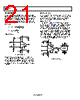
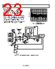
22 / 25 page  AD8251 Rev. B | Page 21 of 24 APPLICATIONS DIFFERENTIAL OUTPUT In certain applications, it is necessary to create a differential signal. High resolution ADCs often require a differential input. In other cases, transmission over a long distance can require differential signals for better immunity to interference. Figure 61 shows how to configure the AD8251 to output a differential signal. An op amp, the AD817, is used in an inverting topology to create a differential voltage. VREF sets the output midpoint according to the equation shown in the figure. Errors from the op amp are common to both outputs and are thus common mode. Likewise, errors from using mismatched resistors cause a common-mode dc offset error. Such errors are rejected in differential signal processing by differential input ADCs or instrumentation amplifiers. When using this circuit to drive a differential ADC, VREF can be set using a resistor divider from the ADC reference to make the output ratiometric with the ADC. SETTING GAINS WITH A MICROCONTROLLER +15V MICRO- CONTROLLER –15V A0 A1 WR +IN –IN 10 μF0.1µF 10 μF0.1µF REF AD8251 + – DGND DGND Figure 60. Programming Gain Using a Microcontroller +12V –12V A0 A1 WR +IN 10 μF 0.1 μF 10 μF 0.1 μF AD8251 REF G = 1 0.1µF 4.99k Ω 4.99k Ω AD817 0.1µF +12V –12V VREF 0V VOUTA = VIN + VREF 2 2 VOUTB = –VIN + VREF +2.5V –2.5V 0V +2.5V –2.5V 0V TIME AMPLITUDE 0V TIME AMPLITUDE +5V –5V AMPLITUDE 10pF +12V –12V VIN + – + – DGND DGND Figure 61. Differential Output with Level Shift |
|
|
링크 URL |
| ALLDATASHEET 가 귀하에 도움이 되셨나요? [ DONATE ] |
Alldatasheet는? | 광고문의 | 운영자에게 연락하기 | 개인정보취급방침 | 링크 투 데이터시트 | 링크교환 | 제조사별 검색 All Rights Reserved©Alldatasheet.com |
| Russian : Alldatasheetru.com | Korean : Alldatasheet.co.kr | Spanish : Alldatasheet.es | French : Alldatasheet.fr | Italian : Alldatasheetit.com Portuguese : Alldatasheetpt.com | Polish : Alldatasheet.pl | Vietnamese : Alldatasheet.vn Indian : Alldatasheet.in | Mexican : Alldatasheet.com.mx | British : Alldatasheet.co.uk | New Zealand : Alldatasheet.co.nz |
|
Family Site : ic2ic.com |
icmetro.com |
 Korean ▼
 English
 Chinese
 German
 Japanese
 Russian
 Korean
 Spanish
 French
 Italian
 Portuguese
 Polish
 Vietnamese
 Indian
 Mexican
 British
 New Zealand