|
전자부품 데이터시트 검색엔진 |
|
|
전자부품 데이터시트 검색엔진 |
|
AL5802 데이터시트(PDF) 7 Page - Diodes Incorporated |
|
|
|||||||||||||||||||||||||||||
AL5802 데이터시트(HTML) 7 Page - Diodes Incorporated |
|
|
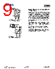
7 / 11 page  AL5802 Document number: DS35516 Rev. 9 - 2 7 of 11 www.diodes.com March 2014 © Diodes Incorporated AL5802 Application Information Fig. 14 Typical Application Circuit for Linear Mode Current Sink LED Driver Fig. 15 Application Circuit for Increasing LED Current The AL5802 has been designed for driving low current LEDs with typical LED current of 20mA to 100mA. It provides a cost effective way for driving low current LEDs compared with more complex switching regulator solutions. Furthermore, it reduces the PCB board area of the solution as there is no need for external components like inductors, capacitors and switching diodes. Figure 14 shows a typical application circuit diagram for driving an LED or string of LEDs. The NPN transistor Q1 measures the LED current by sensing the voltage across an external resistor REXT. Q1 uses its VBE as reference to set the voltage across REXT and controls the base current into Q2. Q2 operates in linear mode to regulate the LED current. The LED current is ILED = VBE(Q1) / REXT From this, for any required LED current the necessary external resistor REXT can be calculated from REXT = VBE(Q1) / ILED Two or more AL5802 can be connected in parallel to construct higher current LED strings as shown in Figure 15. Consideration of the expected linear mode power dissipation must be factored into the design, with respect to the AL5802's thermal resistance. The maximum voltage across the device can be calculated by taking the maximum supply voltage less the voltage across the LED string. VCE(Q2) = VCC – VLED – VBE(Q1) PD = VCE(Q2) * ILED + ( VCC – VBE(Q2) – VBE(Q1)) 2 / R1 As the output current of AL5802 increases, it is necessary to provide appropriate thermal relief to the device. The power dissipation supported by the device is dependent upon the PCB board material, the copper area and the ambient temperature. The maximum dissipation the device can handle is given by: PD = ( TJ(MAX) - TA) /RθJA Refer to the thermal characteristic graphs on page 4 for selecting the appropriate PCB copper area. |
|
|
링크 URL |
| ALLDATASHEET 가 귀하에 도움이 되셨나요? [ DONATE ] |
Alldatasheet는? | 광고문의 | 운영자에게 연락하기 | 개인정보취급방침 | 링크 투 데이터시트 | 링크교환 | 제조사별 검색 All Rights Reserved©Alldatasheet.com |
| Russian : Alldatasheetru.com | Korean : Alldatasheet.co.kr | Spanish : Alldatasheet.es | French : Alldatasheet.fr | Italian : Alldatasheetit.com Portuguese : Alldatasheetpt.com | Polish : Alldatasheet.pl | Vietnamese : Alldatasheet.vn Indian : Alldatasheet.in | Mexican : Alldatasheet.com.mx | British : Alldatasheet.co.uk | New Zealand : Alldatasheet.co.nz |
|
Family Site : ic2ic.com |
icmetro.com |
 Korean ▼
 English
 Chinese
 German
 Japanese
 Russian
 Korean
 Spanish
 French
 Italian
 Portuguese
 Polish
 Vietnamese
 Indian
 Mexican
 British
 New Zealand