|
전자부품 데이터시트 검색엔진 |
|
|
전자부품 데이터시트 검색엔진 |
|
AD9959/PCBZ 데이터시트(PDF) 41 Page - Analog Devices |
|
|
|||||||||||||||||||||||||||||
AD9959/PCBZ 데이터시트(HTML) 41 Page - Analog Devices |
|
|
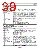
41 / 44 page  Data Sheet AD9959 Rev. C | Page 41 of 44 DESCRIPTIONS FOR CHANNEL REGISTERS Channel Function Register (CFR)—Address 0x03 Three bytes are assigned to this register. Table 34. Bit Descriptions for CFR Bit Mnemonic Description 23:22 Amplitude frequency phase (AFP) select Controls what type of modulation is to be performed for that channel. See the Modulation Mode section for details. 21:16 Open 15 Linear sweep no-dwell 0 = the linear sweep no-dwell function is inactive (default). 1 = the linear sweep no-dwell function is active. If CFR[15] is active, the linear sweep no-dwell function is activated. See the Linear Sweep Mode section for details. If CFR[14] is clear, this bit is don’t care. 14 Linear sweep enable 0 = the linear sweep capability is inactive (default). 1 = the linear sweep capability is enabled. When enabled, the delta frequency tuning word is applied to the frequency accumulator at the programmed ramp rate. 13 Load SRR at I/O_UPDATE 0 = the linear sweep ramp rate timer is loaded only upon timeout (timer = 1) and is not loaded because of an I/O_UPDATE input signal (default). 1 = the linear sweep ramp rate timer is loaded upon timeout (timer = 1) or at the time of an I/O_UPDATE input signal. 12:11 Open 10 Must be 0 Must be set to 0. 9:8 DAC full-scale current control 11 = the DAC is at the largest LSB value (default). See Table 5 for other settings. 7 Digital power-down 0 = the digital core is enabled for operation (default). 1 = the digital core is disabled and is in its lowest power dissipation state. 6 DAC power-down 0 = the DAC is enabled for operation (default). 1 = the DAC is disabled and is in its lowest power dissipation state. 5 Matched pipe delays 0 = matched pipe delay mode is inactive (default). active 1 = matched pipe delay mode is active. See the Single-Tone Mode—Matched Pipeline Delay section for details. 4 Autoclear sweep accumulator 0 = the current state of the sweep accumulator is not impacted by receipt of an I/O_UPDATE signal (default). 1 = t he sweep accumulator is automatically and synchronously cleared for one cycle upon receipt of an I/O_UPDATE signal. 3 Clear sweep 0 = the sweep accumulator functions as normal (default). accumulator 1 = the sweep accumulator memory elements are asynchronously cleared. 2 Autoclear phase accumulator 0 = t he current state of the phase accumulator is not impacted by receipt of an I/O_UPDATE signal (default). 1 = t he phase accumulator is automatically and synchronously cleared for one cycle upon receipt of an I/O_UPDATE signal. 1 Clear phase 0 = the phase accumulator functions as normal (default). accumulator 1 = the phase accumulator memory elements are asynchronously cleared. 0 Sine wave output 0 = the angle-to-amplitude conversion logic employs a cosine function (default). enable 1 = the angle-to-amplitude conversion logic employs a sine function. |
|
링크 URL |
| ALLDATASHEET 가 귀하에 도움이 되셨나요? [ DONATE ] |
Alldatasheet는? | 광고문의 | 운영자에게 연락하기 | 개인정보취급방침 | 링크 투 데이터시트 | 링크교환 | 제조사별 검색 All Rights Reserved©Alldatasheet.com |
| Russian : Alldatasheetru.com | Korean : Alldatasheet.co.kr | Spanish : Alldatasheet.es | French : Alldatasheet.fr | Italian : Alldatasheetit.com Portuguese : Alldatasheetpt.com | Polish : Alldatasheet.pl | Vietnamese : Alldatasheet.vn Indian : Alldatasheet.in | Mexican : Alldatasheet.com.mx | British : Alldatasheet.co.uk | New Zealand : Alldatasheet.co.nz |
|
Family Site : ic2ic.com |
icmetro.com |
 Korean ▼
 English
 Chinese
 German
 Japanese
 Russian
 Korean
 Spanish
 French
 Italian
 Portuguese
 Polish
 Vietnamese
 Indian
 Mexican
 British
 New Zealand