|
전자부품 데이터시트 검색엔진 |
|
|
전자부품 데이터시트 검색엔진 |
|
ST72361 데이터시트(PDF) 43 Page - STMicroelectronics |
|
|
|||||||||||||||||||||||||||||
ST72361 데이터시트(HTML) 43 Page - STMicroelectronics |
|
|
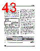
43 / 224 page  ST72361 43/224 POWER SAVING MODES (Cont’d) 8.6 AUTO WAKE-UP FROM HALT MODE Auto Wake-Up From Halt (AWUFH) mode is simi- lar to Halt mode with the addition of an internal RC oscillator for wake-up. Compared to ACTIVE HALT mode, AWUFH has lower power consump- tion because the main clock is not kept running, but there is no accurate realtime clock available. It is entered by executing the HALT instruction when the AWUEN bit in the AWUCSR register has been set and the OIE bit in the MCCSR register is cleared (see section 10.2 on page 59 for more de- tails). Figure 29. AWUFH Mode Block Diagram As soon as HALT mode is entered, and if the AWUEN bit has been set in the AWUCSR register, the AWU RC oscillator provides a clock signal (fAWU_RC). Its frequency is divided by a fixed divid- er and a programmable prescaler controlled by the AWUPR register. The output of this prescaler pro- vides the delay time. When the delay has elapsed the AWUF flag is set by hardware and an interrupt wakes up the MCU from Halt mode. At the same time the main oscillator is immediately turned on and a 256 or 4096 cycle delay is used to stabilize it. After this start-up delay, the CPU resumes oper- ation by servicing the AWUFH interrupt. The AWU flag and its associated interrupt are cleared by software reading the AWUCSR register. To compensate for any frequency dispersion of the AWU RC oscillator, it can be calibrated by measuring the clock frequency fAWU_RC and then calculating the right prescaler value. Measurement mode is enabled by setting the AWUM bit in the AWUCSR register in Run mode. This connects fAWU_RC to the ICAP1 input of the 16-bit timer, al- lowing the fAWU_RC to be measured using the main oscillator clock as a reference timebase. Similarities with Halt mode The following AWUFH mode behavior is the same as normal Halt mode: – The MCU can exit AWUFH mode by means of any interrupt with exit from Halt capability or a re- set (see Section 1.4 HALT MODE). – When entering AWUFH mode, the I[1:0] bits in the CC register are forced to 10b to enable inter- rupts. Therefore, if an interrupt is pending, the MCU wakes up immediately. – In AWUFH mode, the main oscillator is turned off causing all internal processing to be stopped, in- cluding the operation of the on-chip peripherals. None of the peripherals are clocked except those which get their clock supply from another clock generator (such as an external or auxiliary oscil- lator like the AWU oscillator). – The compatibility of Watchdog operation with AWUFH mode is configured by the WDGHALT option bit in the option byte. Depending on this setting, the HALT instruction when executed while the Watchdog system is enabled, can gen- erate a Watchdog RESET. Figure 30. AWUF Halt Timing Diagram AWU RC AWUFH fAWU_RC AWUFH (ei0 source) oscillator prescaler interrupt /64 divider to Timer input capture /1 .. 255 AWUFH interrupt fCPU RUN MODE HALT MODE 256 or 4096 tCPU RUN MODE fAWU_RC Clear by software tAWU |
|
링크 URL |
| ALLDATASHEET 가 귀하에 도움이 되셨나요? [ DONATE ] |
Alldatasheet는? | 광고문의 | 운영자에게 연락하기 | 개인정보취급방침 | 링크 투 데이터시트 | 링크교환 | 제조사별 검색 All Rights Reserved©Alldatasheet.com |
| Russian : Alldatasheetru.com | Korean : Alldatasheet.co.kr | Spanish : Alldatasheet.es | French : Alldatasheet.fr | Italian : Alldatasheetit.com Portuguese : Alldatasheetpt.com | Polish : Alldatasheet.pl | Vietnamese : Alldatasheet.vn Indian : Alldatasheet.in | Mexican : Alldatasheet.com.mx | British : Alldatasheet.co.uk | New Zealand : Alldatasheet.co.nz |
|
Family Site : ic2ic.com |
icmetro.com |
 Korean ▼
 English
 Chinese
 German
 Japanese
 Russian
 Korean
 Spanish
 French
 Italian
 Portuguese
 Polish
 Vietnamese
 Indian
 Mexican
 British
 New Zealand