|
전자부품 데이터시트 검색엔진 |
|
|
전자부품 데이터시트 검색엔진 |
|
TDA4VEN...Q1 데이터시트(PDF) 10 Page - Texas Instruments |
|
|
|||||||||||||||||||||||||||||
TDA4VEN...Q1 데이터시트(HTML) 10 Page - Texas Instruments |
|
|
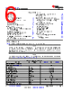
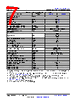
10 / 236 page  • PWR = Power • GND = Ground • CAP = LDO Capacitor. 6. DSIS: The deselected input state (DSIS) indicates the state driven to the subsystem input (logic "0", logic "1", or "pad" level) when the pin multiplexed signal function is not selected by MUXMODE. • 0: Logic 0 driven to the subsystem input. • 1: Logic 1 driven to the subsystem input. • pad: Logic state of the pad is driven to the subsystem input. • An empty box means Not Applicable. 7. BALL STATE DURING RESET (RX/TX/PULL): State of the terminal while MCU_PORz is asserted, where RX defines the state of the input buffer, TX defines the state of the output buffer, and PULL defines the state of internal pull resistors: • RX (Input buffer) – Off: The input buffer is disabled. – On: The input buffer is enabled. • TX (Output buffer) – Off: The output buffer is disabled. – Low: The output buffer is enabled and drives VOL. • PULL (Internal pull resistors) – Off: Internal pull resistors are turned off. – Up: Internal pull-up resistor is turned on. – Down: Internal pull-down resistor is turned on. – NA: Not Applicable. • An empty box means Not Applicable. 8. BALL STATE AFTER RESET (RX/TX/PULL): State of the terminal after MCU_PORz is deasserted, where RX defines the state of the input buffer, TX defines the state of the output buffer, and PULL defines the state of internal pull resistors: • RX (Input buffer) – Off: The input buffer is disabled. – On: The input buffer is enabled. • TX (Output buffer) – Off: The output buffer is disabled. – SS: The subsystem selected with MUXMODE determines the output buffer state. • PULL (Internal pull resistors) – Off: Internal pull resistors are turned off. – Up: Internal pull-up resistor is turned on. – Down: Internal pull-down resistor is turned on. – NA: Not Applicable. • An empty box means Not Applicable. 9. MUX MODE AFTER RESET: The value found in this column defines the default pin multiplexed signal function after MCU_PORz is deasserted. An empty box means Not Applicable. 10. I/O VOLTAGE VALUE: This column describes I/O operating voltage options of the respective power supply, when applicable. An empty box means Not Applicable. For more information, see valid operating voltage range(s) defined for each power supply in Section 6.4, Recommended Operating Conditions. 11. POWER: The power supply of the associated I/O, when applicable. TDA4VEN-Q1, TDA4AEN-Q1 SPRSP96A – MARCH 2024 – REVISED SEPTEMBER 2024 www.ti.com 10 Submit Document Feedback Copyright © 2024 Texas Instruments Incorporated Product Folder Links: TDA4VEN-Q1 TDA4AEN-Q1 |
|
링크 URL |
| ALLDATASHEET 가 귀하에 도움이 되셨나요? [ DONATE ] |
Alldatasheet는? | 광고문의 | 운영자에게 연락하기 | 개인정보취급방침 | 링크 투 데이터시트 | 링크교환 | 제조사별 검색 All Rights Reserved©Alldatasheet.com |
| Russian : Alldatasheetru.com | Korean : Alldatasheet.co.kr | Spanish : Alldatasheet.es | French : Alldatasheet.fr | Italian : Alldatasheetit.com Portuguese : Alldatasheetpt.com | Polish : Alldatasheet.pl | Vietnamese : Alldatasheet.vn Indian : Alldatasheet.in | Mexican : Alldatasheet.com.mx | British : Alldatasheet.co.uk | New Zealand : Alldatasheet.co.nz |
|
Family Site : ic2ic.com |
icmetro.com |
 Korean ▼
 English
 Chinese
 German
 Japanese
 Russian
 Korean
 Spanish
 French
 Italian
 Portuguese
 Polish
 Vietnamese
 Indian
 Mexican
 British
 New Zealand