|
전자부품 데이터시트 검색엔진 |
|
|
전자부품 데이터시트 검색엔진 |
|
LTC3716 데이터시트(PDF) 8 Page - Linear Technology |
|
|
|||||||||||||||||||||||||||||
LTC3716 데이터시트(HTML) 8 Page - Linear Technology |
|
|
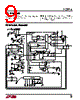
8 / 28 page  8 LTC3716 PI FU CTIO S RUN/SS (Pin 1): Combination of Soft-Start, Run Control Input and Short-Circuit Detection Timer. A capacitor to ground at this pin sets the ramp time to full current output. Forcing this pin below 0.8V causes the IC to shut down all internal circuitry. All functions are disabled in shutdown. SENSE1+, SENSE2+ (Pins 2,14): The (+) Input to Each Differential Current Comparator. The ITH pin voltage and built-in offsets between SENSE– and SENSE+ pins in conjunction with RSENSE set the current trip threshold. SENSE1–, SENSE2– (Pins 3,13): The (–) Input to the Differential Current Comparators. EAIN (Pin 4): Input to the error amplifier that compares the feedback voltage to the internal 0.6V reference voltage. This pin is normally connected to a resistive divider from the output of the differential amplifier (DIFFOUT). PLLFLTR (Pin 5): The phase-locked loop’s lowpass filter is tied to this pin. Alternatively, this pin can be driven with an AC or DC voltage source to vary the frequency of the internal oscillator. Do not apply voltage to this pin prior to application of VIN. PLLIN (Pin 6): External Synchronization Input to Phase Detector. This pin is internally terminated to SGND with 50k Ω. The phase-locked loop will force the rising top gate signal of controller 1 to be synchronized with the rising edge of the PLLIN signal. FCB (Pin 7): Forced Continuous Control Input. This input acts on both output stages and can be used to regulate a secondary winding. Pulling this pin below 0.6V will force continuous synchronous operation. Do not leave this pin floating without a decoupling capacitor. ITH (Pin 8): Error Amplifier Output and Switching Regula- tor Compensation Point. Both current comparator’s thresh- olds increase with this control voltage. The normal voltage range of this pin is from 0V to 2.4V SGND (Pin 9): Signal Ground. This pin is common to both controllers. Route separately to the PGND pin. VDIFFOUT (Pin 10): Output of a Differential Amplifier. This pin provides true remote output voltage sensing. VDIFFOUT normally drives an external resistive divider that sets the output voltage. VOS–, VOS+ (Pins 11, 12): Inputs to an Operational Ampli- fier. Internal precision resistors configure it as a differen- tial amplifier whose output is VDIFFOUT. ATTENOUT (Pin 15): Voltage Feedback Signal Resistively Divided According to the VID Programming Code. ATTENIN (Pin 16): The Input to the VID Controlled Resis- tive Divider. VID0–VID4 (Pins 17,18, 19, 20, 21): VID Control Logic Input Pins. VBIAS (Pin 22): Supply Pin for the VID Control Circuit. AMPMD (Pin 23): This Logic Input pin controls the con- nections of internal precision resistors that configure the operational amplifier as a unity-gain differential amplifier. TG2, TG1 (Pins 24, 35): High Current Gate Drives for Top N-Channel MOSFETS. These are the outputs of floating drivers with a voltage swing equal to INTVCC superim- posed on the switch node voltage SW. SW2, SW1 (Pins 25, 34): Switch Node Connections to Inductors. Voltage swing at these pins is from a Schottky diode (external) voltage drop below ground to VIN. BOOST2, BOOST1 (Pins 26, 33): Bootstrapped Supplies to the Topside Floating Drivers. External capacitors are con- nected between the BOOST and SW pins, and Schottky diodes are connected between the BOOST and INTVCC pins. BG2, BG1 (Pins 27, 31): High Current Gate Drives for Bottom N-Channel MOSFETS. Voltage swing at these pins is from ground to INTVCC. PGND (Pin 28): Driver Power Ground. Connect to sources of bottom N-channel MOSFETS and the (–) terminals of CIN. INTVCC (Pin 29): Output of the Internal 5V Linear Low Dropout Regulator and the EXTVCC Switch. The driver and control circuits are powered from this voltage source. Decouple to power ground with a 1 µF ceramic capacitor placed directly adjacent to the IC and minimum of 4.7 µF additional tantalum or other low ESR capacitor. EXTVCC (Pin 30): External Power Input to an Internal Switch. This switch closes and supplies INTVCC, bypass- ing the internal low dropout regulator whenever EXTVCC is higher than 4.7V. See EXTVCC Connection in the Applica- tions Information section. Do not exceed 7V on this pin and ensure VEXTVCC ≤ VINTVCC. |
|
|
링크 URL |
| ALLDATASHEET 가 귀하에 도움이 되셨나요? [ DONATE ] |
Alldatasheet는? | 광고문의 | 운영자에게 연락하기 | 개인정보취급방침 | 링크 투 데이터시트 | 링크교환 | 제조사별 검색 All Rights Reserved©Alldatasheet.com |
| Russian : Alldatasheetru.com | Korean : Alldatasheet.co.kr | Spanish : Alldatasheet.es | French : Alldatasheet.fr | Italian : Alldatasheetit.com Portuguese : Alldatasheetpt.com | Polish : Alldatasheet.pl | Vietnamese : Alldatasheet.vn Indian : Alldatasheet.in | Mexican : Alldatasheet.com.mx | British : Alldatasheet.co.uk | New Zealand : Alldatasheet.co.nz |
|
Family Site : ic2ic.com |
icmetro.com |
 Korean ▼
 English
 Chinese
 German
 Japanese
 Russian
 Korean
 Spanish
 French
 Italian
 Portuguese
 Polish
 Vietnamese
 Indian
 Mexican
 British
 New Zealand