|
전자부품 데이터시트 검색엔진 |
|
|
전자부품 데이터시트 검색엔진 |
|
FP2207R1-R230-R 데이터시트(PDF) 32 Page - Vicor Corporation |
|
|
|||||||||||||||||||||||||||||
FP2207R1-R230-R 데이터시트(HTML) 32 Page - Vicor Corporation |
|
|
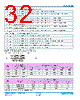
32 / 41 page  Cool-Power® ZVS Switching Regulators Rev 1.5 Page 32 of 41 03/2018 PI352x-00 θ INT-TOP the thermal impedance from the hottest component inside the SiP to the top side θ INT-PCB the thermal impedance from the hottest component inside the SiP to the customer PCB, assuming all pins are at one temperature. θ INT-VIN the thermal impedance from the hottest component inside the SiP to the circuit board VIN pads. θ INT-VS1 the thermal impedance from the hottest component inside the SiP to the circuit board VS1 pads. θ INT-PGND1 the thermal impedance from the hottest component inside the SiP to the circuit board at the PGND1 pads. PGND1 is pins 12A-K. θ INT-PGND2 the thermal impedance from the hottest component inside the SiP to the circuit board at the PGND2 pads . PGND2 is pins 2F-J, 3F-J, 4C-J, 5B-J and 6C-K. θ INT-SGND the thermal impedance from the hottest component inside the SiP to the circuit board at the SGND pads. The following equation can predict the junction temperature based on the heat load applied to the SiP and the known ambient conditions with the simplified thermal circuit model: + + 1 θ INT-TOP 1 θ INT-PCB T TOP θ INT-TOP T PCB θ INT-PCB PD + (1) T INT = Product System Simplified SiP Thermal Impedances Detailed SiP Thermal Impedances θ INT-TOP (°C / W) θ INT-PCB (°C / W) θ INT-TOP (°C / W) θ INT-VIN (°C / W) θ INT-VS1 (°C / W) θ INT-PGND1 (°C / W) θ INT-PGND2 (°C / W) θ INT-SGND (°C / W) PI3523 69.9 0.98 69.9 3.43 1.74 9.81 27.45 86.72 PI3525 68.7 1.477 68.7 3.34 3.76 22.61 19.78 58.78 PI3526 108 1.79 108.25 3.40 5.75 23.80 26.65 86.44 Table 2 — PI352x-00 SiP Thermal Impedance Where the symbol in Figure 89(a) and (b) is defined as the following: θ INT-TOP the thermal impedance from the hot spot to the top surface of the core. θ INT-BOT the thermal impedance from the hot spot to the bottom surface of the core. θ INT-TAB the thermal impedance from the hot spot to the metal mounting tab on the core body, if applicable. θ INT-LEAD1 the thermal impedance from the hot spot to one of the mounting leads. Since the leads are the same thermal impedance, there is no need to specify by explicit pin number. θ INT-LEAD2 the thermal impedance from the hot spot to the other mounting lead. Where the symbol in Figure 89(c) is defined as the following: Table 3 — Inductor effective thermal model parameters Product System Inductor Part Number Effective Thermal Impedances θ INT-TOP (°C / W) θ INT-LEAD1, θINT-LEAD2 (°C / W) θ INT-BOTTOM (°C / W) θ INT-TAB (°C / W) PI3523 FP2207R1-R230-R 11.01 9.42 6.87 n/a PI3525 FP2207R1-R230-R 8.75 9.54 5.99 n/a PI3526 HCV1707R1-R48-R 65.41 17.74 20.46 703 |
|
링크 URL |
| ALLDATASHEET 가 귀하에 도움이 되셨나요? [ DONATE ] |
Alldatasheet는? | 광고문의 | 운영자에게 연락하기 | 개인정보취급방침 | 링크 투 데이터시트 | 링크교환 | 제조사별 검색 All Rights Reserved©Alldatasheet.com |
| Russian : Alldatasheetru.com | Korean : Alldatasheet.co.kr | Spanish : Alldatasheet.es | French : Alldatasheet.fr | Italian : Alldatasheetit.com Portuguese : Alldatasheetpt.com | Polish : Alldatasheet.pl | Vietnamese : Alldatasheet.vn Indian : Alldatasheet.in | Mexican : Alldatasheet.com.mx | British : Alldatasheet.co.uk | New Zealand : Alldatasheet.co.nz |
|
Family Site : ic2ic.com |
icmetro.com |
 Korean ▼
 English
 Chinese
 German
 Japanese
 Russian
 Korean
 Spanish
 French
 Italian
 Portuguese
 Polish
 Vietnamese
 Indian
 Mexican
 British
 New Zealand