|
전자부품 데이터시트 검색엔진 |
|
|
전자부품 데이터시트 검색엔진 |
|
FP2207R1-R230-R 데이터시트(PDF) 34 Page - Vicor Corporation |
|
|
|||||||||||||||||||||||||||||
FP2207R1-R230-R 데이터시트(HTML) 34 Page - Vicor Corporation |
|
|
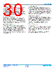
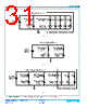
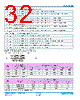
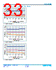
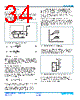
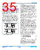
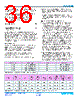
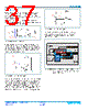
34 / 41 page  Cool-Power® ZVS Switching Regulators Rev 1.5 Page 34 of 41 03/2018 PI352x-00 Application Description Output Voltage Set Point The PI352x-00 family of Buck Regulators utilizes VREF, an internal reference for regulating the output voltage. The output voltage setting is accomplished using external resistors as shown in Figure 93. Select R2 to be at or around 1kΩ for best noise immunity. Use Equations 2 and 3 to determine the proper value based on the desired output voltage. Note: When using the above method of trimming by adjusting the value of R1, the compensation of the control loops is modified and additional Cout may be needed depending on the model. When the PI3526-00-LGIZ is trimmed below 10V, the effective COUT must be at least 120µF, including tolerance and voltage coefficient. Soft Start Adjust and Tracking The TRK pin offers a means to increase the regulator’s soft-start time or to track with additional regulators. The soft-start slope is controlled by an internal capacitor and a fixed charge current to provide a Soft-Start Time tSS for all PI352x-00 regulators. By adding an additional external capacitor to the TRK pin, the soft-start time can be increased further. The following equation can be used to calculate the proper capacitor for a desired soft-start time in excess of tSS: where tTRK is the soft-start time and ITRK is a 50µA internal charge current (see Electrical Characteristics for limits). In applications such as battery or super-capacitor charging where the load is pre-biased, the PI352x can start into output voltages up to the externally applied trim set point, or the minimum absolute OVP, provided the value does not exceed 6V. For start up into loads which are pre-biased above 6V, an ORing FET or equivalent sub-circuit is required to decouple the buck output from the load during start up. In any application with a CV type load, the regulator must be configured in a constant-current mode of operation; the built-in current limit is a fault protection only. There is typically either proportional or direct tracking implemented within a design. For proportional tracking between several regulators at start up, simply connect all PI352x-00 device TRK pins together. This type of tracking will force all connected regulators to start up and reach regulation at the same time (see Figure 94a). For Direct Tracking, choose the PI352x-00 with the highest output voltage as the master and connect the master to the TRK pin of the other PI352x-00 regulators through a divider (Figure 95) with the same ratio as the slave’s feedback divider. All connected PI352x-00 regulator soft-start slopes will track with this method. Direct tracking timing is demonstrated in Figure 94b. All tracking regulators should have their Enable (EN) pins connected together to work properly. Figure 93 — External resistor divider network EAO EAIN + - V REF C EAIN-INT COMP V OUT R ZI C HF R1 R2 V OUT = VREF • R1 + R2 R2 (2) R1 = R2 • V OUT – VREF V REF (3) where V REF = VEAIN (4) C TRK = (tTRK • ITRK ) – CTRK_INT Figure 94 — PI352x-00 tracking responses V OUT 1 V OUT 2 Master V OUT V OUT 2 (a) (b) t Figure 95 — Voltage divider connections for direct tracking Master V OUT R1 R2 SGND TRK PI352x Slave |
|
링크 URL |
| ALLDATASHEET 가 귀하에 도움이 되셨나요? [ DONATE ] |
Alldatasheet는? | 광고문의 | 운영자에게 연락하기 | 개인정보취급방침 | 링크 투 데이터시트 | 링크교환 | 제조사별 검색 All Rights Reserved©Alldatasheet.com |
| Russian : Alldatasheetru.com | Korean : Alldatasheet.co.kr | Spanish : Alldatasheet.es | French : Alldatasheet.fr | Italian : Alldatasheetit.com Portuguese : Alldatasheetpt.com | Polish : Alldatasheet.pl | Vietnamese : Alldatasheet.vn Indian : Alldatasheet.in | Mexican : Alldatasheet.com.mx | British : Alldatasheet.co.uk | New Zealand : Alldatasheet.co.nz |
|
Family Site : ic2ic.com |
icmetro.com |
 Korean ▼
 English
 Chinese
 German
 Japanese
 Russian
 Korean
 Spanish
 French
 Italian
 Portuguese
 Polish
 Vietnamese
 Indian
 Mexican
 British
 New Zealand