|
전자부품 데이터시트 검색엔진 |
|
|
전자부품 데이터시트 검색엔진 |
|
ADP1611ARMZ-R7 데이터시트(PDF) 13 Page - Analog Devices |
|
|
|||||||||||||||||||||||||||||
ADP1611ARMZ-R7 데이터시트(HTML) 13 Page - Analog Devices |
|
|
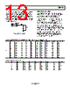
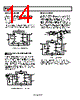
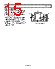
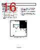
13 / 20 page  ADP1611 Rev. 0 | Page 13 of 20 For low ESR output capacitance, such as with a ceramic capaci- tor, C2 is optional. For optimal transient performance, the RCOMP and CCOMP might need to be adjusted by observing the load transient response of the ADP1611. For most applications, the compensation resistor should be in the range of 30 kΩ to 400 kΩ, and the compensation capacitor should be in the range of 100 pF to 1.2 nF. Table 7 shows external component values for several applications. REF COMP FB C2 CC RC ERROR AMP 1 2 gm Figure 26. Compensation Components SOFT-START CAPACITOR The voltage at SS ramps up slowly by charging the soft-start capacitor (CSS) with an internal 3 µA current source. Table 8 lists the values for the soft-start period, based on maximum output current and maximum switching frequency. The soft-start capacitor limits the rate of voltage rise on the COMP pin, which in turn limits the peak switch current at startup. Table 8 shows a typical soft-start period, tSS, at maximum output current, IOUT_MAX, for several conditions. A 20 nF soft-start capacitor results in negligible input current overshoot at startup, and so is suitable for most applications. However, if an unusually large output capacitor is used, a longer soft-start period is required to prevent input inrush current. Conversely, if fast startup is a requirement, the soft-start capacitor can be reduced or even removed, allowing the ADP1611 to start quickly, but allowing greater peak switch current (see Figure 24 and Figure 25). Table 7. Recommended External Components for Popular Input/Output Voltage Conditions VIN (V) VOUT (V) fSW (MHz) L (µH) COUT (µF) CIN (µF) R1 (kΩ) R2 (kΩ) RCOMP (kΩ) CCOMP (pF) IOUT_MAX (mA) 3.3 5 0.70 4.7 10 10 30.9 10 50 520 600 5 1.23 2.7 10 10 30.9 10 90.9 150 600 9 0.70 10 10 10 63.4 10 71.5 820 350 9 1.23 4.7 10 10 63.4 10 150 180 350 12 0.70 10 10 10 88.7 10 130 420 250 12 1.23 4.7 10 10 88.7 10 280 100 250 5 9 0.70 10 10 10 63.4 10 84.5 390 450 9 1.23 4.7 10 10 63.4 10 178 100 450 12 0.70 10 10 10 88.7 10 140 220 350 12 1.23 4.7 10 10 88.7 10 300 100 350 20 0.70 10 10 10 154 10 400 100 250 20 1.23 6.8 10 10 154 10 400 100 250 Table 8. Typical Soft Start Period VIN (V) VOUT (V) COUT (µF) CSS (nF) tSS (ms) VIN (V) VOUT (V) COUT (µF) CSS (nF) tSS (ms) 3.3 5 10 20 0.3 5 9 10 20 0.4 5 10 100 2 9 10 100 1.5 9 10 20 2.5 12 10 20 0.62 9 10 100 8.2 12 10 100 2 12 10 20 3.5 20 10 20 1.1 12 10 100 15 20 10 100 4.1 |
|
|
링크 URL |
| ALLDATASHEET 가 귀하에 도움이 되셨나요? [ DONATE ] |
Alldatasheet는? | 광고문의 | 운영자에게 연락하기 | 개인정보취급방침 | 링크 투 데이터시트 | 링크교환 | 제조사별 검색 All Rights Reserved©Alldatasheet.com |
| Russian : Alldatasheetru.com | Korean : Alldatasheet.co.kr | Spanish : Alldatasheet.es | French : Alldatasheet.fr | Italian : Alldatasheetit.com Portuguese : Alldatasheetpt.com | Polish : Alldatasheet.pl | Vietnamese : Alldatasheet.vn Indian : Alldatasheet.in | Mexican : Alldatasheet.com.mx | British : Alldatasheet.co.uk | New Zealand : Alldatasheet.co.nz |
|
Family Site : ic2ic.com |
icmetro.com |
 Korean ▼
 English
 Chinese
 German
 Japanese
 Russian
 Korean
 Spanish
 French
 Italian
 Portuguese
 Polish
 Vietnamese
 Indian
 Mexican
 British
 New Zealand