|
전자부품 데이터시트 검색엔진 |
|
|
전자부품 데이터시트 검색엔진 |
|
SI53112-A00AGMR 데이터시트(PDF) 9 Page - Skyworks Solutions Inc. |
|
|
|||||||||||||||||||||||||||||
SI53112-A00AGMR 데이터시트(HTML) 9 Page - Skyworks Solutions Inc. |
|
|
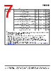
9 / 35 page  Si53112 Skyworks Solutions, Inc. • Phone [781] 376-3000 • Fax [781] 376-3100 • sales@skyworksinc.com • www.skyworksinc.com 9 Rev. 1.1 • Skyworks Proprietary Information • Products and Product Information are Subject to Change Without Notice • September 2, 2021 Ringback Voltage Vrb 0.2 N/A V 3,8 Notes: 1. Unless otherwise noted, all specifications in this table apply to all processor frequencies. 2. This is the time from the valid CLK_IN input clocks and the assertion of the PWRGD signal level at 1.8–2.0 V to the time that stable clocks are output from the buffer chip (PLL locked). 3. Test configuration is Rs = 33.2 , Rp = 49.9, 2 pF for 100 transmission line; Rs = 27 , Rp = 42.2, 2 pF for 85 transmission line. 4. Measurement taken from differential waveform. 5. Using frequency counter with the measurement interval equal or greater than 0.15 s, target frequencies are 99,750,00 Hz, 133,000,000 Hz. 6. The average period over any 1 µs period of time must be greater than the minimum and less than the maximum specified period. 7. Measure taken from differential waveform on a component test board. The edge (slew) rate is measured from –150 mV to +150 mV on the differential waveform . Scope is set to average because the scope sample clock is making most of the dynamic wiggles along the clock edge Only valid for Rising clock and Falling CLOCK. Signal must be monotonic through the Vol to Voh region for Trise and Tfall. 8. Measurement taken from single-ended waveform. 9. Measured with oscilloscope, averaging off, using min max statistics. Variation is the delta between min and max. 10. Measured with oscilloscope, averaging on, The difference between the rising edge rate (average) of clock verses the falling edge rate (average) of CLOCK. 11. Rise/Fall matching is derived using the following, 2*(Trise - Tfall) / (Trise + Tfall). 12. VHigh is defined as the statistical average High value as obtained by using the Oscilloscope VHigh Math function. 13. VLow is defined as the statistical average Low value as obtained by using the Oscilloscope VLow Math function. 14. Measured at crossing point where the instantaneous voltage value of the rising edge of CLK equals the falling edge of CLK. 15. This measurement refers to the total variation from the lowest crossing point to the highest, regardless of which edge is crossing. 16. The crossing point must meet the absolute and relative crossing point specifications simultaneously. 17. Vcross(rel) Min and Max are derived using the following, Vcross(rel) Min = 0.250 + 0.5 (Vhavg – 0.700), Vcross(rel) Max = 0.550 – 0.5 (0.700 – Vhavg), (see Figures 3-4 for further clarification). 18. Vcross is defined as the total variation of all crossing voltages of Rising CLOCK and Falling CLOCK. This is the maximum allowed variance in Vcross for any particular system. 19. Overshoot is defined as the absolute value of the maximum voltage. 20. Undershoot is defined as the absolute value of the minimum voltage. Table 5. DIF 0.7 V AC Timing Characteristics (Non-Spread Spectrum Mode)1 (Continued) Parameter Symbol CLK 100 MHz, 133 MHz Unit Notes Min Typ Max |
|
링크 URL |
| ALLDATASHEET 가 귀하에 도움이 되셨나요? [ DONATE ] |
Alldatasheet는? | 광고문의 | 운영자에게 연락하기 | 개인정보취급방침 | 링크 투 데이터시트 | 링크교환 | 제조사별 검색 All Rights Reserved©Alldatasheet.com |
| Russian : Alldatasheetru.com | Korean : Alldatasheet.co.kr | Spanish : Alldatasheet.es | French : Alldatasheet.fr | Italian : Alldatasheetit.com Portuguese : Alldatasheetpt.com | Polish : Alldatasheet.pl | Vietnamese : Alldatasheet.vn Indian : Alldatasheet.in | Mexican : Alldatasheet.com.mx | British : Alldatasheet.co.uk | New Zealand : Alldatasheet.co.nz |
|
Family Site : ic2ic.com |
icmetro.com |
 Korean ▼
 English
 Chinese
 German
 Japanese
 Russian
 Korean
 Spanish
 French
 Italian
 Portuguese
 Polish
 Vietnamese
 Indian
 Mexican
 British
 New Zealand