|
전자부품 데이터시트 검색엔진 |
|
|
전자부품 데이터시트 검색엔진 |
|
SC2453 데이터시트(PDF) 12 Page - Semtech Corporation |
|
|
|||||||||||||||||||||||||||||
SC2453 데이터시트(HTML) 12 Page - Semtech Corporation |
|
|
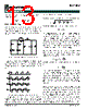
12 / 22 page  12 2005 Semtech Corp. www.semtech.com SC2453 POWER MANAGEMENT o esr ESR I R v δ = ∆ Aluminum capacitors (e.g. electrolytic, solid OS-CON, POSCAP, tantalum) have high capacitances and low ESL’s. The ESR has the dominant effect on the output ripple voltage. It is therefore very important to minimize the ESR. When determining the ESR value, both the steady state ripple-voltage and the dynamic load transient need to be considered. To keep the steady state output ripple-voltage < ∆V o, the ESR should satisfy: o o 1 esr I V R δ ∆ < To limit the dynamic output voltage overshoot/ undershoot within α (say 3%) of the steady state output voltage) from no load to full load, the ESR value should satisfy: o o 2 esr I V R α < Then, the required ESR value of the output capacitors should be: R esr = min{Resr1,Resr2 } The voltage rating of aluminum capacitors should be at least 1.5V o. The RMS current ripple rating should also be greater than: 3 2 I o δ Usually it is necessary to have several capacitors of the same type in parallel to satisfy the ESR requirement. The voltage ripple cause by the capacitor charge/ discharge should be an order of magnitude smaller than the voltage ripple caused by the ESR. To guarantee this, the capacitance should satisfy: esr s o R f 2 10 C π > In many applications, several low ESR ceramic capacitors are added in parallel with the aluminum capacitors in order to further reduce ESR and improve high frequency decoupling. Because the values of capacitance and ESR are usually different in ceramic and aluminum capacitors, the following remarks are made to clarify some practical issues. Remark 1: High frequency ceramic capacitors may not carry most of the ripple current. It also depends on the capacitor value. Only when the capacitor value is set properly, the effect of ceramic capacitor low ESR starts to be significant. For example, if a 10 µF, 4mΩ ceramic capacitor is connected in parallel with 2x1500 µF, 90mΩ electrolytic capacitors, the ripple current in the ceramic capacitor is only about 42% of the current in the electrolytic capacitors at the ripple frequency. If a 100 µF, 2mΩ ceramic capacitor is used, the ripple current in the ceramic capacitor will be about 4.2 times of that in the electrolytic capacitors. When two 100 µF, 2mΩ ceramic capacitors are used, the current ratio increases to 8.3. In this case most of the ripple current flows in the ceramic decoupling capacitor. The ESR of the ceramic capacitors will then determine the output ripple-voltage. Remark 2: The total equivalent capacitance of the filter bank is not simply the sum of all the paralleled capacitors. The total equivalent ESR is not simply the parallel combination of all the individual ESR’s either. Instead they should be calculated using the following formulae. ) C C ( C C ) C R C R ( ) C C ( C C ) R R ( : ) ( C b 1 a 1 b 1 a 1 2 b 1 2 b 1 a 1 2 a 1 2 b 1 a 1 2 b 1 2 a 1 2 2 b 1 a 1 eq + + ω + + + ω + = ω 2 b 1 a 1 2 b 1 2 a 1 2 2 b 1 a 1 2 a 1 a 1 2 b 1 b 1 2 b 1 2 a 1 2 b 1 a 1 b 1 a 1 eq ) C C ( C C ) R R ( ) C R C R ( C C ) R R ( R R : ) ( R + + ω + + + ω + = ω where R 1a and C1a are the ESR and capacitance of electrolytic capacitors, and R 1b and C1b are the ESR and capacitance of the ceramic capacitors respectively. (Figure 2) C1a R1a C1b R1b Ceq Req Figure 2. Equivalent RC branch. Req and Ceq are both functions of frequency. For rigorous design, the equivalent ESR should be evaluated at the ripple frequency for voltage ripple calculation when both ceramic and electrolytic capacitors are used. If R 1a = R1b |
|
|
링크 URL |
| ALLDATASHEET 가 귀하에 도움이 되셨나요? [ DONATE ] |
Alldatasheet는? | 광고문의 | 운영자에게 연락하기 | 개인정보취급방침 | 링크 투 데이터시트 | 링크교환 | 제조사별 검색 All Rights Reserved©Alldatasheet.com |
| Russian : Alldatasheetru.com | Korean : Alldatasheet.co.kr | Spanish : Alldatasheet.es | French : Alldatasheet.fr | Italian : Alldatasheetit.com Portuguese : Alldatasheetpt.com | Polish : Alldatasheet.pl | Vietnamese : Alldatasheet.vn Indian : Alldatasheet.in | Mexican : Alldatasheet.com.mx | British : Alldatasheet.co.uk | New Zealand : Alldatasheet.co.nz |
|
Family Site : ic2ic.com |
icmetro.com |
 Korean ▼
 English
 Chinese
 German
 Japanese
 Russian
 Korean
 Spanish
 French
 Italian
 Portuguese
 Polish
 Vietnamese
 Indian
 Mexican
 British
 New Zealand