|
전자부품 데이터시트 검색엔진 |
|
|
전자부품 데이터시트 검색엔진 |
|
ADBMS1818ASWAZ-R7 데이터시트(PDF) 26 Page - Analog Devices |
|
|
|||||||||||||||||||||||||||||
ADBMS1818ASWAZ-R7 데이터시트(HTML) 26 Page - Analog Devices |
|
|
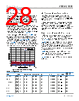
26 / 92 page  Data Sheet ADBMS1818 THEORY OF OPERATION analog.com Rev. B | 26 of 92 ISOSPI STATE DESCRIPTIONS The ADBMS1818 has two isoSPI ports (Port A and Port B) for daisy-chain communication. Idle State In the idle state, the isoSPI ports are powered down. When isoSPI Port A or Port B receives a wake-up signal (see the Waking Up the Serial Interface section), the isoSPI enters the ready state. This transition happens quickly (within tREADY) if the core is in the standby state. If the core is in the sleep state when the isoSPI receives a wake-up signal, the core transitions to the ready state within tWAKE. Ready State In the ready state, the isoSPI port(s) are ready for communication. The serial interface current in the ready state depends on the status of the ISOMD pin and RBIAS = RB1 + RB2 (the external resistors tied to the IBIAS pin). If there is no activity (that is, no wake-up signal) on Port A or Port B for greater than tIDLE, the ADBMS1818 enters the idle state. When the serial interface is transmitting or receiving data, the ADBMS1818 enters the active state. Active State In the active state, the ADBMS1818 is transmitting and receiving data using one or both of the isoSPI ports. The serial interface consumes maximum power in the active state. The supply current increases with clock frequency as the density of isoSPI pulses increases. POWER CONSUMPTION The ADBMS1818 is powered via two pins: V+ and VREG. The V+ input requires voltage greater than or equal to the top cell voltage minus 0.3 V and provides power to the high voltage elements of the core circuits. The VREG input requires 5 V and provides power to the remaining core circuits and the isoSPI circuitry. The VREG input can be powered through an external transistor, driven by the regulated DRIVE output pin. Alternatively, VREG can be powered by an external supply. The power consumption varies according to the operational states. Table 17 and Table 18 provide equations to approximate the supply pin currents in each state. The V+ pin current depends only on the core state. However, the VREG pin current depends on both the core state and isoSPI state, and can therefore be divided into two components. The isoSPI interface draws current only from the VREG pin. IREG = IREG(CORE) + IREG(isoSPI) In the sleep state, the VREG pin draws approximately 3.1 μA if powered by an external supply. Otherwise, the V+ pin supplies the necessary current. Table 17. Core Supply Current State IVP IREG(CORE) Sleep VREG = 0 V 6.1 µA 0 µA VREG = 5 V 3 µA 3.1 µA Standby 14 µA 35 µA REFUP 550 µA 900 µA Measure 950 µA 15 mA Table 18. isoSPI Supply Current Equations isoSPI State ISOMD Connection IREG(isoSPI) Idle Not applicable 0 mA Ready VREG 2.2 mA + 3 × IB V− 1.5 mA + 3 × IB Active VREG Write: 2.5mA + 3 + 20 × 100nstCLK × IB Read: 2.5mA + 3 + 20 × 100ns ×1.5 tCLK × IB V− 1.8mA + 3 + 20 × 100nstCLK × IB |
|
링크 URL |
| ALLDATASHEET 가 귀하에 도움이 되셨나요? [ DONATE ] |
Alldatasheet는? | 광고문의 | 운영자에게 연락하기 | 개인정보취급방침 | 링크 투 데이터시트 | 링크교환 | 제조사별 검색 All Rights Reserved©Alldatasheet.com |
| Russian : Alldatasheetru.com | Korean : Alldatasheet.co.kr | Spanish : Alldatasheet.es | French : Alldatasheet.fr | Italian : Alldatasheetit.com Portuguese : Alldatasheetpt.com | Polish : Alldatasheet.pl | Vietnamese : Alldatasheet.vn Indian : Alldatasheet.in | Mexican : Alldatasheet.com.mx | British : Alldatasheet.co.uk | New Zealand : Alldatasheet.co.nz |
|
Family Site : ic2ic.com |
icmetro.com |
 Korean ▼
 English
 Chinese
 German
 Japanese
 Russian
 Korean
 Spanish
 French
 Italian
 Portuguese
 Polish
 Vietnamese
 Indian
 Mexican
 British
 New Zealand