|
전자부품 데이터시트 검색엔진 |
|
|
전자부품 데이터시트 검색엔진 |
|
PA162 데이터시트(PDF) 5 Page - Cirrus Logic |
|
|
|||||||||||||||||||||||||||||
PA162 데이터시트(HTML) 5 Page - Cirrus Logic |
|
|
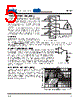
5 / 6 page  PA162 PA162U 5 P r o d u c t I n n o v a t i o n F r o m TYPICALAPPLICATION(CONT) The amplifiers are especially well-suited for applications such as this. The extended common mode range allows command inputs as low as 0V. The output swing lets it drive within 2V of the supply at an output of 1A. This means that a command input that ranges from 0 to 10V will drive a 24V motor from full scale CCW to full scale CW at ±1A. -Vs (pins 11, 15, 16 and 20) must be tied to the heatslug externally on the PCB. To ease metal routing on the PCB, run a direct trace from the -Vs pin to the center heat slug. The PA162 can be used in a three amplifier configuration for a three phase inverter or motor as shown in Figure 4. GENERAL Please read Application Note 1 "General Operating Con- siderations" which covers stability, supplies, heatsinking, mounting, SOA interpretation, and specification interpre- tation. Visit www.cirrus.com for design tools that help automate tasks such as calculations for stability, internal power dissipation, heatsink selection; Apex Precision Power's complete Application Notes library; Technical Semi- nar Workbook; and Evaluation Kits. STABILITYCONSIDERATIONS All monolithic power op amps use output stage topologies that present special sta- bility problems. This is primarily due to non-complementary (both devices are NPN) output stages with a mismatch in gain and phase response for different polarities of output current. It is difficult for the op amp manufacturer to optimize compensation for all operating conditions. For applications with load current exceeding 300mA, oscillation may appear. The oscillation may occur only with the output voltage swing at the negative or positive half cycle. Under most operating and load conditions acceptable stability can be achieved by providing a series RC snubber network connected from the output to ground (see Figure 5). The recommended component values of the network are, R SN = 10Ω and CSN = 0.01µF. Please refer to Application Note 1 for further details. SAFEOPERATINGAREA(SOA) The SOA curves combine the effect of all limits for this power op amp. For a given application, the direction and magnitude of the output current should be calculated or measured and checked against the SOA curves. This is simple for resistive loads but more complex for reactive and EMF generating loads. The following guidelines may save extensive analytical efforts. SUPPLY TO OUTPUT DIFFERENTIAL VOLTAGE, V S - VO (V) SOA 4 AMPLIFIERS LOADED 1 AMPLIFIER LOADED 2 AMPLIFIERS LOADED 3 AMPLIFIERS LOADED DC, T C = 25°C DC, T C = 85°C 1 50 10 0.1 10 1 N o S PA162 Quad Using 3 amplifiers from PA162 as 3 phase motor driver. FIGURE4.3PhaseInverter – + C SN 0.01µF R SN 10Ω FIGURE5.R-CSnubber |
|
|
링크 URL |
| ALLDATASHEET 가 귀하에 도움이 되셨나요? [ DONATE ] |
Alldatasheet는? | 광고문의 | 운영자에게 연락하기 | 개인정보취급방침 | 링크 투 데이터시트 | 링크교환 | 제조사별 검색 All Rights Reserved©Alldatasheet.com |
| Russian : Alldatasheetru.com | Korean : Alldatasheet.co.kr | Spanish : Alldatasheet.es | French : Alldatasheet.fr | Italian : Alldatasheetit.com Portuguese : Alldatasheetpt.com | Polish : Alldatasheet.pl | Vietnamese : Alldatasheet.vn Indian : Alldatasheet.in | Mexican : Alldatasheet.com.mx | British : Alldatasheet.co.uk | New Zealand : Alldatasheet.co.nz |
|
Family Site : ic2ic.com |
icmetro.com |
 Korean ▼
 English
 Chinese
 German
 Japanese
 Russian
 Korean
 Spanish
 French
 Italian
 Portuguese
 Polish
 Vietnamese
 Indian
 Mexican
 British
 New Zealand