|
전자부품 데이터시트 검색엔진 |
|
|
전자부품 데이터시트 검색엔진 |
|
ADP1660ACBZ-R7 데이터시트(PDF) 14 Page - Analog Devices |
|
|
|||||||||||||||||||||||||||||
ADP1660ACBZ-R7 데이터시트(HTML) 14 Page - Analog Devices |
|
|
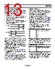
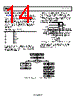
14 / 28 page  ADP1660 Data Sheet Rev. 0 | Page 14 of 28 BATTERY INPUT DC CURRENT LIMIT The ADP1660 has an optional programmable input dc current limit that limits the maximum battery current used over all con- ditions. This feature allows higher LED currents to be used in a system with significant variation in LED forward voltage (VF) and supply battery voltage without the risk of exceeding the current allocated to the flash. To enable the input dc current limit, set the IL_DC_EN bit (Bit 0) in Register 0x03. To set the input dc current limit, use the IL_DC bits (Bits[3:1]) in Register 0x03 (see Table 10). Table 10. Input DC Current Limit IL_DC Bit Value DC Current Limit (A) 000 1.0 001 1.25 010 1.5 011 1.75 100 2.0 (default) 101 2.25 110 2.5 111 2.75 During startup of the flash, if the battery current does not exceed the dc current limit, the LED1 and LED2 currents are set to the values of the I_FL1 and I_FL2 bits in Register 0x06 and Register 0x09, respectively. If the battery current exceeds the programmed dc current limit on startup, the LED current does not increase further. The dc current limit flag is set in the fault information register (Bit 0 of Register 0x0C). The FL_I_FL1 bits in Register 0x0D and the FL_I_FL2 bits in Register 0x0E are set to the actual LED current values and are available for readback. REG 0x02, FL_TIM = XXXXms REG 0x06, I_FL1 = XX XXXXmA REG 0x09, I_FL2 = XX XXXXmA REG 0x03, IL_DC_EN = 1 IL_DC = XX A I2C DATA BUS STROBE PROGRAMMED LED CURRENT ACTUAL LED CURRENT ADP1660 SETS FL_IDC (REG 0x0C) TO 1. ADP1660 SETS FL_I_FL1 (REG 0x0D) TO ACTUAL LED CURRENT. ADP1660 SETS LED1_EN TO 0. ADP1660 SETS LED2_EN TO 0. ADP1660 SETS LED_MOD TO 000. REG 0x0F, LED1_EN = 1 LED2_EN = 1 REG 0x01, STR_LV = 1 LED_MOD = 011 ADP1660 SETS FL_I_FL2 (REG 0x0E) TO ACTUAL LED CURRENT. Figure 25. DC Current Limit Operation in a Low Battery, High LED VF Case The camera system shown in Figure 26 can adjust the image sensor settings based on the known reduced LED current for a low battery and a high VF LED. SELECT FLASH CURRENT SELECT MAX BATTERY CURRENT PREFLASH STROBE DC LIMIT EXCEEDED? LED CURRENT = PROGRAMMED LED CURRENT NO LED CURRENT LOCKED AT CURRENT VALUE YES BATTERY CURRENT = PROGRAMMED DC LIMIT READ LED CURRENT (REG 0x0D AND REG 0x0E) ADJUST IMAGE SENSOR STROBE STROBE Figure 26. Use of the DC Current Limit in an Optimized Camera System |
|
|
링크 URL |
| ALLDATASHEET 가 귀하에 도움이 되셨나요? [ DONATE ] |
Alldatasheet는? | 광고문의 | 운영자에게 연락하기 | 개인정보취급방침 | 링크 투 데이터시트 | 링크교환 | 제조사별 검색 All Rights Reserved©Alldatasheet.com |
| Russian : Alldatasheetru.com | Korean : Alldatasheet.co.kr | Spanish : Alldatasheet.es | French : Alldatasheet.fr | Italian : Alldatasheetit.com Portuguese : Alldatasheetpt.com | Polish : Alldatasheet.pl | Vietnamese : Alldatasheet.vn Indian : Alldatasheet.in | Mexican : Alldatasheet.com.mx | British : Alldatasheet.co.uk | New Zealand : Alldatasheet.co.nz |
|
Family Site : ic2ic.com |
icmetro.com |
 Korean ▼
 English
 Chinese
 German
 Japanese
 Russian
 Korean
 Spanish
 French
 Italian
 Portuguese
 Polish
 Vietnamese
 Indian
 Mexican
 British
 New Zealand