|
전자부품 데이터시트 검색엔진 |
|
|
전자부품 데이터시트 검색엔진 |
|
ADP1660ACBZ-R7 데이터시트(PDF) 23 Page - Analog Devices |
|
|
|||||||||||||||||||||||||||||
ADP1660ACBZ-R7 데이터시트(HTML) 23 Page - Analog Devices |
|
|
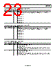
23 / 28 page  Data Sheet ADP1660 Rev. 0 | Page 23 of 28 Table 25. LED1 Flash Current Fault Readback Register (Register 0x0D) Bits Bit Name Access Description [7:6] Reserved R Reserved. [5:0] FL_I_FL1 R These bits contain the flash current value for LED1 when the dc current limit fault occurs. The current setting is equal to the value of these six bits multiplied by 12.5 mA (FL_I_FL1 × 12.5). 00 0000 = 0 mA. 00 0001 = 12.5 mA. … 00 1000 = 100 mA. … 01 0100 = 250 mA. … 10 1000 = 500 mA. … 11 1100 = 750 mA. Table 26. LED2 Flash Current Fault Readback Register (Register 0x0E) Bits Bit Name Access Description [7:6] Reserved R Reserved. [5:0] FL_I_FL2 R These bits contain the flash current value for LED2 when the dc current limit fault occurs. The current setting is equal to the value of these six bits multiplied by 12.5 mA (FL_I_FL2 × 12.5). 00 0000 = 0 mA. 00 0001 = 12.5 mA. … 00 1000 = 100 mA. … 01 0100 = 250 mA. … 10 1000 = 500 mA. … 11 1100 = 750 mA. Table 27. LED Enable Mode Register (Register 0x0F) Bits Bit Name Access Description [7:2] Reserved R/W Reserved. 1 LED2_EN R/W This bit enables or disables the LED2 output. 0 = disable LED2 output (default). 1 = enable LED2 output. To enable both channels at once, set both LED2_EN and LED1_EN to 0 and then set both bits to 1 in the same I2C write command. If LED1 is already enabled and the user tries to set the LED2_EN bit to 1, this write is ignored. 0 LED1_EN R/W This bit enables or disables the LED1 output. 0 = disable LED1 output (default). 1 = enable LED1 output. To enable both channels at once, set both LED1_EN and LED2_EN to 0 and then set both bits to 1 in the same I2C write command. If LED2 is already enabled and the user tries to set the LED1_EN bit to 1, this write is ignored. |
|
|
링크 URL |
| ALLDATASHEET 가 귀하에 도움이 되셨나요? [ DONATE ] |
Alldatasheet는? | 광고문의 | 운영자에게 연락하기 | 개인정보취급방침 | 링크 투 데이터시트 | 링크교환 | 제조사별 검색 All Rights Reserved©Alldatasheet.com |
| Russian : Alldatasheetru.com | Korean : Alldatasheet.co.kr | Spanish : Alldatasheet.es | French : Alldatasheet.fr | Italian : Alldatasheetit.com Portuguese : Alldatasheetpt.com | Polish : Alldatasheet.pl | Vietnamese : Alldatasheet.vn Indian : Alldatasheet.in | Mexican : Alldatasheet.com.mx | British : Alldatasheet.co.uk | New Zealand : Alldatasheet.co.nz |
|
Family Site : ic2ic.com |
icmetro.com |
 Korean ▼
 English
 Chinese
 German
 Japanese
 Russian
 Korean
 Spanish
 French
 Italian
 Portuguese
 Polish
 Vietnamese
 Indian
 Mexican
 British
 New Zealand