|
전자부품 데이터시트 검색엔진 |
|
|
전자부품 데이터시트 검색엔진 |
|
AT86RF211DAI-R 데이터시트(PDF) 18 Page - ATMEL Corporation |
|
|
|||||||||||||||||||||||||||||
AT86RF211DAI-R 데이터시트(HTML) 18 Page - ATMEL Corporation |
|
|
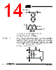
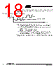
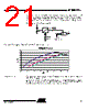
18 / 48 page  18 AT86RF211 1942C–WIRE–06/02 To operate this way, the user must make sure that the "0" and "1" level at the output of the discriminator are "on both sides" of the comparison level in order for the decision to be made properly. Figure 22. How toSet Up theDataSlicing Parameters To set the discriminator and the Data Slicer accordingly: – It is possible to measure the output DC level of the discriminator DISCOUT (thanks to the A/D embedded converter) – DTR[1:0] make it possible to shift (up or down) the DC level at the output of the discriminator : - DTR[1] = 1: +180 mV + 77x (V CC -2.4V) - DTR[0] = 1: -180 mV - 77x (V CC -2.4V) – DTR[5:2] make it possible to tune the comparison threshold around V CC/2. 16 levels are possible, with a LSB = 15 mV per Volt of supply voltage. V CC/2 corresponds to DTR[5:2] = 0111, and the RESET value is 1000. These procedures can be made automatically by software. Please refer to the applica- tion note. DISCOUT: demodulated data Not OK Comparator threshold Time OK |
|
링크 URL |
| ALLDATASHEET 가 귀하에 도움이 되셨나요? [ DONATE ] |
Alldatasheet는? | 광고문의 | 운영자에게 연락하기 | 개인정보취급방침 | 링크 투 데이터시트 | 링크교환 | 제조사별 검색 All Rights Reserved©Alldatasheet.com |
| Russian : Alldatasheetru.com | Korean : Alldatasheet.co.kr | Spanish : Alldatasheet.es | French : Alldatasheet.fr | Italian : Alldatasheetit.com Portuguese : Alldatasheetpt.com | Polish : Alldatasheet.pl | Vietnamese : Alldatasheet.vn Indian : Alldatasheet.in | Mexican : Alldatasheet.com.mx | British : Alldatasheet.co.uk | New Zealand : Alldatasheet.co.nz |
|
Family Site : ic2ic.com |
icmetro.com |
 Korean ▼
 English
 Chinese
 German
 Japanese
 Russian
 Korean
 Spanish
 French
 Italian
 Portuguese
 Polish
 Vietnamese
 Indian
 Mexican
 British
 New Zealand