|
전자부품 데이터시트 검색엔진 |
|
|
전자부품 데이터시트 검색엔진 |
|
AT86RF211DAI-R 데이터시트(PDF) 4 Page - ATMEL Corporation |
|
|
|||||||||||||||||||||||||||||
AT86RF211DAI-R 데이터시트(HTML) 4 Page - ATMEL Corporation |
|
|
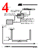
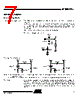
4 / 48 page  4 AT86RF211 1942C–WIRE–06/02 Figure 2. Wake-up Overview Figure 3. Periodical Scan Header + Address Step 3: If a correct header is received (mandatory) and address matches (if any), the data field is then stored into AT86RF211 and WAKEUP pin is activated (to wake-up the Microcontroller). The Microcontroller will then read the data into one of its registers, and begin a relevant procedure. Note: Data field is optional: the chip can be simply woken-up with no dedicated data. AT86RF211 (TRX01) Wake-up mode 3 Companion Microcontroller WAKEUP pin Step 2: The chip wakes-up periodically, waiting for an expected message (stand-alone operation) Step 1: The chip is set up in sleep mode using the 3-wire interface (SLE, SCK, SDATA), then Microcontroller goes to sleep, waiting for an interrupt on WAKEUP pin Data stored Data field Reception mode Short reception window Oscillator settling Sleep mode Wake Up period Timing Power Consumption |
|
링크 URL |
| ALLDATASHEET 가 귀하에 도움이 되셨나요? [ DONATE ] |
Alldatasheet는? | 광고문의 | 운영자에게 연락하기 | 개인정보취급방침 | 링크 투 데이터시트 | 링크교환 | 제조사별 검색 All Rights Reserved©Alldatasheet.com |
| Russian : Alldatasheetru.com | Korean : Alldatasheet.co.kr | Spanish : Alldatasheet.es | French : Alldatasheet.fr | Italian : Alldatasheetit.com Portuguese : Alldatasheetpt.com | Polish : Alldatasheet.pl | Vietnamese : Alldatasheet.vn Indian : Alldatasheet.in | Mexican : Alldatasheet.com.mx | British : Alldatasheet.co.uk | New Zealand : Alldatasheet.co.nz |
|
Family Site : ic2ic.com |
icmetro.com |
 Korean ▼
 English
 Chinese
 German
 Japanese
 Russian
 Korean
 Spanish
 French
 Italian
 Portuguese
 Polish
 Vietnamese
 Indian
 Mexican
 British
 New Zealand