|
전자부품 데이터시트 검색엔진 |
|
|
전자부품 데이터시트 검색엔진 |
|
TDA3602 데이터시트(PDF) 13 Page - NXP Semiconductors |
|
|
|||||||||||||||||||||||||||||
TDA3602 데이터시트(HTML) 13 Page - NXP Semiconductors |
|
|
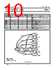
13 / 26 page  July 1994 13 Philips Semiconductors Product specification Multiple output voltage regulator TDA3602 APPLICATION INFORMATION Noise Table 3 Noise at regulator outputs dependent on capacitive load (CL). Note 1. Regulators loaded with 100mA; noise in µV RMS (B = 10 Hz to 1 MHz). The available noise at the output of the regulators depends on the bandwidth of the regulators, which can be adjusted by means of the load capacitors. The noise figures are given in Table 3. Although stability is guarenteed when CL is higher than 10 µF (over temperature range) with tan (φ) = 1 in the frequency range 1 kHz to 20 kHz, it is recommended to use a 47 µF load capacitor for Regulators 1 and 2. When a microprocessor is supplied by Regulator 3 much noise can be produced by this microprocessor. This noise is not influenced by increasing the load capacitor of Regulator 3. The noise on the supply line depends on the supply capacitor. When a high frequency capacitor of 220 nF with an electrolytic capacitor of 100 µF in parallel is placed directly over pin 1 (VP) and pin 6 (ground) the noise is minimized. The stabilizer is in 'power on' after the supply is reconnected (Vbu> 7.9 V) and 0.1 < Vsc < 2.2 V. Application circuits STABILIZER WITHOUT MICROPROCESSOR 1 The low end application is illustrated in Fig.7. When switch SW1 is closed, a pulse is generated at the state control input by C5 and R1, and the regulator is switched from power off to the on mode (all three regulators are on). The HOLD signal can be used to control the mute signal for the power amplifiers. This signal is HIGH when all the regulators are in regulation and VP1 Schmitt trigger is true. REGULATOR (NOTE 1) CL REG IL 10 µF47 µF 220 µF 1 150 mA 800 µV 220 µV 160 µV 2 100 mA 500 µV115 µV 3 50 mA 350 µV 190 µV STABILIZER WITHOUT MICROPROCESSOR 2 Fig.8 illustrates the application circuit for a low end radio set with push switches when no microprocessor is used. The stabilizer can be switched to the on mode by pressing switch SW1. In this mode, Regulators 1 and 2 are switched on, so transistor T1 takes over from switch SW1. The stabilizer can only be switched off by connecting the base of T1 to ground (SW1 not pressed). This can be achieved by pressing switch SW2. The hold signal is only HIGH when the device is in the on mode and both VP and the regulators are available, so that this signal can be used to control the power stages (mute). During a fault condition, this signal turns LOW immediately. When the stabilizer is connected to the supply for the first time, the initial state will be the power-on stage, so Regulators 1 and 2 are not switched on. STABILIZER USED WITH MICROPROCESSOR For a good understanding of the high end application, shown in Fig.10, consult the flow chart of Fig.9. When the set is off, a reset can be generated by connecting the set to the supply for the first time (stabilizer in power-on), or by pressing any key on the key matrix (stabilizer in reset mode). When the reset is generated, the stabilizer is held in the reset mode for a short period by T1. The microprocessor has to take over control by making reset mode equal to 0. The microprocessor can then proceed with the initializing process. After this action, the microprocessor has to check if the correct key has been pressed. If so, the radio can be switched on by making on equal to 0; if not, the microprocessor must switch the device to the coma mode again, by making reset mode and on both equal to 1; (wake mode is entered after a short time constant, determined by R1 × C7 × constant), and switch itself to sleep mode. When the reset is generated for the first time (power-on mode), the mode of the device can be detected by the hold signal. If on = 0 and hold remains LOW, then the microprocessor is in the power-on mode. In this event, the microprocessor must go to the switch-off routine (making on and reset mode both equal to 1). |
|
|
링크 URL |
| ALLDATASHEET 가 귀하에 도움이 되셨나요? [ DONATE ] |
Alldatasheet는? | 광고문의 | 운영자에게 연락하기 | 개인정보취급방침 | 링크 투 데이터시트 | 링크교환 | 제조사별 검색 All Rights Reserved©Alldatasheet.com |
| Russian : Alldatasheetru.com | Korean : Alldatasheet.co.kr | Spanish : Alldatasheet.es | French : Alldatasheet.fr | Italian : Alldatasheetit.com Portuguese : Alldatasheetpt.com | Polish : Alldatasheet.pl | Vietnamese : Alldatasheet.vn Indian : Alldatasheet.in | Mexican : Alldatasheet.com.mx | British : Alldatasheet.co.uk | New Zealand : Alldatasheet.co.nz |
|
Family Site : ic2ic.com |
icmetro.com |
 Korean ▼
 English
 Chinese
 German
 Japanese
 Russian
 Korean
 Spanish
 French
 Italian
 Portuguese
 Polish
 Vietnamese
 Indian
 Mexican
 British
 New Zealand