|
전자부품 데이터시트 검색엔진 |
|
|
전자부품 데이터시트 검색엔진 |
|
TDA3602 데이터시트(PDF) 17 Page - NXP Semiconductors |
|
|
|||||||||||||||||||||||||||||
TDA3602 데이터시트(HTML) 17 Page - NXP Semiconductors |
|
|
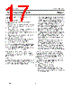
17 / 26 page  July 1994 17 Philips Semiconductors Product specification Multiple output voltage regulator TDA3602 Example of a modern car radio design with the TDA3602 DESIGN CONSIDERATIONS A modern car radio set meets the following design considerations: 1. Semi on/off logic. The radio set has to switch on/off by pressing the on/off key or by switching the ignition 2. Security code check 3. Low quiescent current in standby (this means that the microprocessor is off when the set is off) 4. The set must recover the state it had before an engine start or load dump 5. Apart from HOLD, RESET and VP only two more I/O lines are used for full on/off logic 6. Supply by 1 or 2 supply lines 7. Radio Data System (RDS) should be implemented in the set, but this is not a regulator problem 8. Lights must switch off during load dump Although the TDA3602 is designed only to be supplied by a continuous supply (battery), it is also possible to use both a continuous and a switchable supply (ignition). The ignition can be used to supply also the TDA3602, although in this event additional circuitry is needed. APPLICATION CIRCUIT WITH (SEMI-)FULL ON/OFF LOGIC The application circuit of Fig.11 will meet all the above mentioned design considerations. Three circuit parts can be distinguished: Reset circuitry A reset is required to call-up the microprocessor when it is switched to the sleep mode or the power-on reset (first initialization of the microprocessor). To achieve this, three different types of resets should be generated: 1. When the set has been disconnected from the supply, the microprocessor must be initialized at connection to the supply for the first time. The output ports of the microprocessor are in a random state. To ensure correct initialization, a reset has to be generated. This is accomplished by the power-on state of the TDA3602. In this state the reset output is HIGH and Regulators 1 and 2 are disabled (despite the voltage on the state control pin Vsc being below 1.1 V). Only after the voltage on the state control pin has risen above 2.2 V can Regulators 1 and 2 be switched on again by pulling the state control pin below 1.1 V. 2. In the sleep mode the microprocessor should be called up by pressing the on/off key (normal off condition). Now the reset is also generated by the RESET output of the TDA3602. This reset output will go HIGH when Vsc decreases from the value VREG3 to below 1.9 V. 3. At fault conditions (VP below 7.1 V, VREG1 < VREG1 nominal −0.3 V or VP > 1 8 V), HOLD drops to logic 0 and the microprocessor switches off the set. In accordance with the design considerations is that the mode of operation must switch to the state it was in before an engine start or load dump occurred. To achieve this the HOLD output of the TDA3602 can be used to generate a reset pulse (only when Vsc remains below 1.1 V). The RESET and HOLD outputs of the TDA3602 are combined to generate the reset pulses. The pulses are created by differentiating the outputs, using capacitors C8 and C9. The reset pulses are added by means of the diodes D2 and D3. The time constants are: • tresres(rise) = 3 × R7 × C8 = 3 × 10 kΩ × 1uF = 30 ms on/off button S1 should be pressed for at least 30ms, before the microprocessor will see this • treshold(rise) = 3 × R7 × C9 = 5.4 ms • tres(dis) = 3 × R8 × C8 = 140 ms • treshold(disl) = 3 × R9 × C9 = 25 ms the microprocessor has to wait and check if HOLD remains LOW for at least 25 ms before it switches off; now it is certain that a correct reset will occur to wake up the microprocessor again. |
|
|
링크 URL |
| ALLDATASHEET 가 귀하에 도움이 되셨나요? [ DONATE ] |
Alldatasheet는? | 광고문의 | 운영자에게 연락하기 | 개인정보취급방침 | 링크 투 데이터시트 | 링크교환 | 제조사별 검색 All Rights Reserved©Alldatasheet.com |
| Russian : Alldatasheetru.com | Korean : Alldatasheet.co.kr | Spanish : Alldatasheet.es | French : Alldatasheet.fr | Italian : Alldatasheetit.com Portuguese : Alldatasheetpt.com | Polish : Alldatasheet.pl | Vietnamese : Alldatasheet.vn Indian : Alldatasheet.in | Mexican : Alldatasheet.com.mx | British : Alldatasheet.co.uk | New Zealand : Alldatasheet.co.nz |
|
Family Site : ic2ic.com |
icmetro.com |
 Korean ▼
 English
 Chinese
 German
 Japanese
 Russian
 Korean
 Spanish
 French
 Italian
 Portuguese
 Polish
 Vietnamese
 Indian
 Mexican
 British
 New Zealand