|
전자부품 데이터시트 검색엔진 |
|
|
전자부품 데이터시트 검색엔진 |
|
AT45DB021D 데이터시트(PDF) 5 Page - ATMEL Corporation |
|
|
|||||||||||||||||||||||||||||
AT45DB021D 데이터시트(HTML) 5 Page - ATMEL Corporation |
|
|
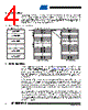
5 / 52 page  5 3638F–DFLASH–4/08 AT45DB021D 6. Read Commands By specifying the appropriate opcode, data can be read from the main memory or from the SRAM data buffer. The DataFlash supports RapidS protocols for Mode 0 and Mode 3. Please refer to the “Detailed Bit-level Read Timing” diagrams in this datasheet for details on the clock cycle sequences for each mode. 6.1 Continuous Array Read (Legacy Command – E8H): Up to 66 MHz By supplying an initial starting address for the main memory array, the Continuous Array Read command can be utilized to sequentially read a continuous stream of data from the device by simply providing a clock signal; no additional addressing information or control signals need to be provided. The DataFlash incorporates an internal address counter that will automatically increment on every clock cycle, allowing one continuous read operation without the need of additional address sequences. To perform a continuous read from the DataFlash standard page size (264 bytes), an opcode of E8H must be clocked into the device followed by three address bytes (which comprise the 24-bit page and byte address sequence) and 4 don’t care bytes. The first 10 bits (PA9 - PA0) of the 19-bit address sequence specify which page of the main memory array to read, and the last 9 bits (BA8 - BA0) of the 19-bit address sequence specify the starting byte address within the page. To perform a continuous read from the binary page size (256 bytes), the opcode (E8H) must be clocked into the device followed by three address bytes and 4 don’t care bytes. The first 10 bits (A17 - A8) of the 18-bits sequence specify which page of the main memory array to read, and the last 8 bits (A7 - A0) of the 18-bits address sequence specify the starting byte address within the page. The don’t care bytes that follow the address bytes are needed to initialize the read operation. Following the don’t care bytes, additional clock pulses on the SCK pin will result in data being output on the SO (serial output) pin. The CS pin must remain low during the loading of the opcode, the address bytes, the don’t care bytes, and the reading of data. When the end of a page in main memory is reached during a Continuous Array Read, the device will continue reading at the beginning of the next page with no delays incurred during the page boundary crossover (the crossover from the end of one page to the beginning of the next page). When the last bit in the main memory array has been read, the device will continue reading back at the beginning of the first page of memory. As with cross- ing over page boundaries, no delays will be incurred when wrapping around from the end of the array to the beginning of the array. A low-to-high transition on the CS pin will terminate the read operation and tri-state the output pin (SO). The maximum SCK frequency allowable for the Continuous Array Read is defined by the f CAR1 specification. The Continuous Array Read bypasses the data buffer and leaves the contents of the buffer unchanged. 6.2 Continuous Array Read (High Frequency Mode – 0BH): Up to 66 MHz This command can be used with the serial interface to read the main memory array sequentially in high speed mode for any clock frequency up to the maximum specified by f CAR1. To perform a continuous read array with the page size set to 264 bytes, the CS must first be asserted then an opcode 0BH must be clocked into the device followed by three address bytes and a dummy byte. The first 10 bits (PA9 - PA0) of the 19-bit address sequence specify which page of the main memory array to read, and the last 9 bits (BA8 - BA0) of the 19-bit address sequence spec- ify the starting byte address within the page. To perform a continuous read with the page size set to 256 bytes, the opcode, 0BH, must be clocked into the device followed by three address bytes (A17 - A0) and a dummy byte. Following the dummy byte, additional clock pulses on the SCK pin will result in data being output on the SO (serial output) pin. |
|
링크 URL |
| ALLDATASHEET 가 귀하에 도움이 되셨나요? [ DONATE ] |
Alldatasheet는? | 광고문의 | 운영자에게 연락하기 | 개인정보취급방침 | 링크 투 데이터시트 | 링크교환 | 제조사별 검색 All Rights Reserved©Alldatasheet.com |
| Russian : Alldatasheetru.com | Korean : Alldatasheet.co.kr | Spanish : Alldatasheet.es | French : Alldatasheet.fr | Italian : Alldatasheetit.com Portuguese : Alldatasheetpt.com | Polish : Alldatasheet.pl | Vietnamese : Alldatasheet.vn Indian : Alldatasheet.in | Mexican : Alldatasheet.com.mx | British : Alldatasheet.co.uk | New Zealand : Alldatasheet.co.nz |
|
Family Site : ic2ic.com |
icmetro.com |
 Korean ▼
 English
 Chinese
 German
 Japanese
 Russian
 Korean
 Spanish
 French
 Italian
 Portuguese
 Polish
 Vietnamese
 Indian
 Mexican
 British
 New Zealand