|
전자부품 데이터시트 검색엔진 |
|
|
전자부품 데이터시트 검색엔진 |
|
TMP86CS49FG 데이터시트(PDF) 53 Page - Toshiba Semiconductor |
|
|
|||||||||||||||||||||||||||||
TMP86CS49FG 데이터시트(HTML) 53 Page - Toshiba Semiconductor |
|
|
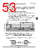
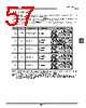
53 / 252 page  Page 39 TMP86CS49FG 3.3 Interrupt Sequence An interrupt request, which raised interrupt latch, is held, until interrupt is accepted or interrupt latch is cleared to “0” by resetting or an instruction. Interrupt acceptance sequence requires 8 machine cycles (2 µs @16 MHz) after the completion of the current instruction. The interrupt service task terminates upon execution of an interrupt return instruction [RETI] (for maskable interrupts) or [RETN] (for non-maskable interrupts). Figure 3-1 shows the timing chart of interrupt acceptance processing. 3.3.1 Interrupt acceptance processing is packaged as follows. a. The interrupt master enable flag (IMF) is cleared to “0” in order to disable the acceptance of any fol- lowing interrupt. b. The interrupt latch (IL) for the interrupt source accepted is cleared to “0”. c. The contents of the program counter (PC) and the program status word, including the interrupt master enable flag (IMF), are saved (Pushed) on the stack in sequence of PSW + IMF, PCH, PCL. Mean- while, the stack pointer (SP) is decremented by 3. d. The entry address (Interrupt vector) of the corresponding interrupt service program, loaded on the vec- tor table, is transferred to the program counter. e. The instruction stored at the entry address of the interrupt service program is executed. Note:When the contents of PSW are saved on the stack, the contents of IMF are also saved. Note 1: a: Return address entry address, b: Entry address, c: Address which RETI instruction is stored Note 2: On condition that interrupt is enabled, it takes 38/fc [s] or 38/fs [s] at maximum (If the interrupt latch is set at the first machine cycle on 10 cycle instruction) to start interrupt acceptance processing since its interrupt latch is set. Figure 3-1 Timing Chart of Interrupt Acceptance/Return Interrupt Instruction Example: Correspondence between vector table address for INTTBT and the entry address of the interrupt service program Figure 3-2 Vector table address,Entry address a b a c + 1 Execute instruction SP PC Execute instruction n n − 2 n - 3 n − 2n − 1 n − 1 n a + 2 a + 1 c + 2 b + 3 b + 2 b + 1 a + 1 a a − 1 Execute RETI instruction Interrupt acceptance Execute instruction Interrupt service task 1-machine cycle Interrupt request Interrupt latch (IL) IMF D2H 03H D203H D204H 06H Vector table address Entry address 0FH Vector Interrupt service program FFF0H FFF1H |
|
링크 URL |
| ALLDATASHEET 가 귀하에 도움이 되셨나요? [ DONATE ] |
Alldatasheet는? | 광고문의 | 운영자에게 연락하기 | 개인정보취급방침 | 링크 투 데이터시트 | 링크교환 | 제조사별 검색 All Rights Reserved©Alldatasheet.com |
| Russian : Alldatasheetru.com | Korean : Alldatasheet.co.kr | Spanish : Alldatasheet.es | French : Alldatasheet.fr | Italian : Alldatasheetit.com Portuguese : Alldatasheetpt.com | Polish : Alldatasheet.pl | Vietnamese : Alldatasheet.vn Indian : Alldatasheet.in | Mexican : Alldatasheet.com.mx | British : Alldatasheet.co.uk | New Zealand : Alldatasheet.co.nz |
|
Family Site : ic2ic.com |
icmetro.com |
 Korean ▼
 English
 Chinese
 German
 Japanese
 Russian
 Korean
 Spanish
 French
 Italian
 Portuguese
 Polish
 Vietnamese
 Indian
 Mexican
 British
 New Zealand