|
전자부품 데이터시트 검색엔진 |
|
|
전자부품 데이터시트 검색엔진 |
|
TMP86CS49FG 데이터시트(PDF) 103 Page - Toshiba Semiconductor |
|
|
|||||||||||||||||||||||||||||
TMP86CS49FG 데이터시트(HTML) 103 Page - Toshiba Semiconductor |
|
|
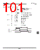
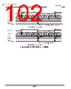
103 / 252 page  Page 89 TMP86CS49FG 8.3.6 Programmable Pulse Generate (PPG) Output Mode In the programmable pulse generation (PPG) mode, an arbitrary duty pulse is generated by counting per- formed in the internal clock. To start the timer, TC1CR<TC1S> specifies either the edge of the input pulse to the TC1 pin or the command start. TC1CR<MPPG1> specifies whether a duty pulse is produced continuously or not (one-shot pulse). • When TC1CR<MPPG1> is set to “0” (Continuous pulse generation) When a match between the up-counter and the TC1DRB value is detected after the timer starts, the level of the PPG pin is inverted and an INTTC1 interrupt request is generated. The up-counter contin- ues counting. When a match between the up-counter and the TC1DRA value is detected, the level of the PPG pin is inverted and an INTTC1 interrupt request is generated. The up-counter is cleared at this time, and then continues counting and pulse generation. When TC1S is cleared to “00” during PPG output, the PPG pin retains the level immediately before the counter stops. • When TC1CR<MPPG1> is set to “1” (One-shot pulse generation) When a match between the up-counter and the TC1DRB value is detected after the timer starts, the level of the PPG pin is inverted and an INTTC1 interrupt request is generated. The up-counter contin- ues counting. When a match between the up-counter and the TC1DRA value is detected, the level of the PPG pin is inverted and an INTTC1 interrupt request is generated. TC1CR<TC1S> is cleared to “00” automatically at this time, and the timer stops. The pulse generated by PPG retains the same level as that when the timer stops. Since the output level of the PPG pin can be set with TC1CR<TFF1> when the timer starts, a positive or neg- ative pulse can be generated. Since the inverted level of the timer F/F1 output level is output to the PPG pin, specify TC1CR<TFF1> to “0” to set the high level to the PPG pin, and “1” to set the low level to the PPG pin. Upon reset, the timer F/F1 is initialized to “0”. Note 1: To change TC1DRA or TC1DRB during a run of the timer, set a value sufficiently larger than the count value of the counter. Setting a value smaller than the count value of the counter during a run of the timer may generate a pulse different from that specified. Note 2: Do not change TC1CR<TFF1> during a run of the timer. TC1CR<TFF1> can be set correctly only at initial- ization (after reset). When the timer stops during PPG, TC1CR<TFF1> can not be set correctly from this point onward if the PPG output has the level which is inverted of the level when the timer starts. (Setting TC1CR<TFF1> specifies the timer F/F1 to the level inverted of the programmed value.) Therefore, the timer F/F1 needs to be initialized to ensure an arbitrary level of the PPG output. To initialize the timer F/F1, change TC1CR<TC1M> to the timer mode (it is not required to start the timer mode), and then set the PPG mode. Set TC1CR<TFF1> at this time. Note 3: In the PPG mode, the following relationship must be satisfied. TC1DRA > TC1DRB Note 4: Set TC1DRB after changing the mode of TC1M to the PPG mode. |
|
링크 URL |
| ALLDATASHEET 가 귀하에 도움이 되셨나요? [ DONATE ] |
Alldatasheet는? | 광고문의 | 운영자에게 연락하기 | 개인정보취급방침 | 링크 투 데이터시트 | 링크교환 | 제조사별 검색 All Rights Reserved©Alldatasheet.com |
| Russian : Alldatasheetru.com | Korean : Alldatasheet.co.kr | Spanish : Alldatasheet.es | French : Alldatasheet.fr | Italian : Alldatasheetit.com Portuguese : Alldatasheetpt.com | Polish : Alldatasheet.pl | Vietnamese : Alldatasheet.vn Indian : Alldatasheet.in | Mexican : Alldatasheet.com.mx | British : Alldatasheet.co.uk | New Zealand : Alldatasheet.co.nz |
|
Family Site : ic2ic.com |
icmetro.com |
 Korean ▼
 English
 Chinese
 German
 Japanese
 Russian
 Korean
 Spanish
 French
 Italian
 Portuguese
 Polish
 Vietnamese
 Indian
 Mexican
 British
 New Zealand