|
전자부품 데이터시트 검색엔진 |
|
|
전자부품 데이터시트 검색엔진 |
|
TMP86CS49FG 데이터시트(PDF) 116 Page - Toshiba Semiconductor |
|
|
|||||||||||||||||||||||||||||
TMP86CS49FG 데이터시트(HTML) 116 Page - Toshiba Semiconductor |
|
|
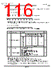
116 / 252 page  Page 102 10. 8-Bit TimerCounter (TC3, TC4) 10.1 Configuration TMP86CS49FG The TimerCounter 4 is controlled by the TimerCounter 4 control register (TC4CR) and two 8-bit timer registers (TTREG4 and PWREG4). Note 1: Do not change the timer register (TTREG4) setting while the timer is running. Note 2: Do not change the timer register (PWREG4) setting in the operating mode except the 8-bit and 16-bit PWM modes while the timer is running. Note 1: fc: High-frequency clock [Hz] fs: Low-frequency clock [Hz] Note 2: Do not change the TC4M, TC4CK and TFF4 settings while the timer is running. Note 3: To stop the timer operation (TC4S= 1 → 0), do not change the TC4M, TC4CK and TFF4 settings. To start the timer operation (TC4S= 0 → 1), TC4M, TC4CK and TFF4 can be programmed. Note 4: When TC4M= 1** (upper byte in the 16-bit mode), the source clock becomes the TC3 overflow signal regardless of the TC4CK setting. Note 5: To use the TimerCounter in the 16-bit mode, select the operating mode by programming TC4M, where TC3CR<TC3M> must be set to 011. TimerCounter 4 Timer Register TTREG4 (0015H) R/W 7 6543 210 (Initial value: 1111 1111) PWREG4 (0019H) R/W 7 6543 210 (Initial value: 1111 1111) TimerCounter 4 Control Register TC4CR (0028H) 7 6543 210 TFF4 TC4CK TC4S TC4M (Initial value: 0000 0000) TFF4 Timer F/F4 control 0: 1: Clear Set R/W TC4CK Operating clock selection [Hz] NORMAL1/2, IDLE1/2 mode SLOW1/2 SLEEP1/2 mode R/W DV7CK = 0 DV7CK = 1 000 fc/211 fs/23 fs/23 001 fc/27 fc/27 – 010 fc/25 fc/25 – 011 fc/23 fc/23 – 100 fs fs fs 101 fc/2 fc/2 – 110 fc fc – 111 TC4 pin input TC4S TC4 start control 0: 1: Operation stop and counter clear Operation start R/W TC4M TC4M operating mode select 000: 001: 010: 011: 100: 101: 110: 111: 8-bit timer/event counter mode 8-bit programmable divider output (PDO) mode 8-bit pulse width modulation (PWM) output mode Reserved 16-bit timer/event counter mode Warm-up counter mode 16-bit pulse width modulation (PWM) output mode 16-bit PPG mode R/W |
|
링크 URL |
| ALLDATASHEET 가 귀하에 도움이 되셨나요? [ DONATE ] |
Alldatasheet는? | 광고문의 | 운영자에게 연락하기 | 개인정보취급방침 | 링크 투 데이터시트 | 링크교환 | 제조사별 검색 All Rights Reserved©Alldatasheet.com |
| Russian : Alldatasheetru.com | Korean : Alldatasheet.co.kr | Spanish : Alldatasheet.es | French : Alldatasheet.fr | Italian : Alldatasheetit.com Portuguese : Alldatasheetpt.com | Polish : Alldatasheet.pl | Vietnamese : Alldatasheet.vn Indian : Alldatasheet.in | Mexican : Alldatasheet.com.mx | British : Alldatasheet.co.uk | New Zealand : Alldatasheet.co.nz |
|
Family Site : ic2ic.com |
icmetro.com |
 Korean ▼
 English
 Chinese
 German
 Japanese
 Russian
 Korean
 Spanish
 French
 Italian
 Portuguese
 Polish
 Vietnamese
 Indian
 Mexican
 British
 New Zealand