|
전자부품 데이터시트 검색엔진 |
|
|
전자부품 데이터시트 검색엔진 |
|
ISL9301 데이터시트(PDF) 5 Page - Intersil Corporation |
|
|
|||||||||||||||||||||||||||||
ISL9301 데이터시트(HTML) 5 Page - Intersil Corporation |
|
|
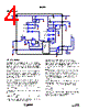
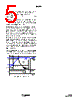
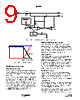
5 / 12 page  5 FN6435.0 February 25, 2008 IREF - Charge-current program and monitoring pin. Connect a resistor between this pin and the GND pin to set the charge current limit determined by Equation 4: Where RIREF is in kΩ. The IREF pin voltage also monitors the actual charge current during the entire charge cycle, including the trickle, constant-current, and constant-voltage phases. When disabled, VIREF = 0V. BATON - Battery disconnect pin. The BATON pin is a logic input pin to allow the disconnection of the battery from the system to eliminate the unwanted drainage current from the battery. There is an internal 1M Ω pull-down resistor at this pin. Drive to HIGH to connect the battery to the system. When this pin is driven to LOW or left floating, the battery is disconnected from the system. VOUT - Output connection to the system. This pin provides a 4.5V regulated voltage for the system when a valid input power is present. If no valid input is present, and BATON is driven HI, the VOUT pin is connected to VBAT through an internal MOSFET. If no valid input is present and BATON is LOW, the voltage at VOUT pin is zero. A 4.7µF or larger X5R ceramic capacitor is recommended for decoupling and stability purposes. EPAD - Exposed pad. Connect as much copper as possible to this pad either on the component layer or other layers through thermal vias to enhance the thermal performance. I REF 3886 R IREF ----------------- mA () = (EQ. 4) FIGURE 1. TYPICAL CHARGING CYCLE IREF Trickle CC CV IMIN 4.2V TIME 2.8V CHG Charge Current Charge Voltage CHG Indication VREC 16%IREF Timeout ISL9301 |
|
|
링크 URL |
| ALLDATASHEET 가 귀하에 도움이 되셨나요? [ DONATE ] |
Alldatasheet는? | 광고문의 | 운영자에게 연락하기 | 개인정보취급방침 | 링크 투 데이터시트 | 링크교환 | 제조사별 검색 All Rights Reserved©Alldatasheet.com |
| Russian : Alldatasheetru.com | Korean : Alldatasheet.co.kr | Spanish : Alldatasheet.es | French : Alldatasheet.fr | Italian : Alldatasheetit.com Portuguese : Alldatasheetpt.com | Polish : Alldatasheet.pl | Vietnamese : Alldatasheet.vn Indian : Alldatasheet.in | Mexican : Alldatasheet.com.mx | British : Alldatasheet.co.uk | New Zealand : Alldatasheet.co.nz |
|
Family Site : ic2ic.com |
icmetro.com |
 Korean ▼
 English
 Chinese
 German
 Japanese
 Russian
 Korean
 Spanish
 French
 Italian
 Portuguese
 Polish
 Vietnamese
 Indian
 Mexican
 British
 New Zealand