|
전자부품 데이터시트 검색엔진 |
|
|
전자부품 데이터시트 검색엔진 |
|
ISL9301 데이터시트(PDF) 7 Page - Intersil Corporation |
|
|
|||||||||||||||||||||||||||||
ISL9301 데이터시트(HTML) 7 Page - Intersil Corporation |
|
|
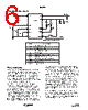
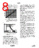
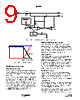
7 / 12 page  7 FN6435.0 February 25, 2008 The ISL9301 accepts an input voltage up to 28V but will be disabled when the input voltage exceeds the OVP threshold, minimum 10V, to protect against unqualified or faulty AC adapters. PPR Indication The PPR pin is an open-drain output to indicate the presence of the AC adapter. Whenever the input voltage is higher than the POR threshold, the PPR pin turns on the internal open-drain MOSFET to indicate a logic LOW signal. When the internal open-drain FET is turned off, the PPR pin should leak less than 1µA current. When turned on, the PPR pin should be able to sink at least 10mA current under all operating conditions. The PPR pin can be used to drive an LED (see “Typical Application Circuit” on page 6) or to interface with a microprocessor. Power-Good Range The power-good range is defined by the following three conditions: 1. VIN > VPOR 2. VIN - VOUT > VOS 3. VIN < VOVP where VOS is the offset voltage for the input and output voltage comparator and the VOVP is the overvoltage protection threshold given in the "Electrical Specifications" starting on page 2. All VPOR, VOS, and VOVP have hysteresis. The IC will not deliver any output if the input voltage is not in the power-good range. CHG Indication The CHG is an open-drain output. The open drain FET turns on when the charger starts to charge and turns off when the EOC condition is qualified. Once the EOC condition is qualified, the CHG signal is latched in off state. The EOC condition is qualified when both of the following conditions are satisfied: 1. VBAT > VRECHG 2. ICHG < IMIN The CHG indication will not be turned on again until a recharge condition is qualified. A recharge condition is reached under one of the three conditions: 1. Input power being re-cycled 2. Enable signal being toggled 3. A recharge cycle starts when the battery voltage drops below the recharge threshold The CHG signal can be interfaced either with a micro-processor GPIO or a LED for indication. A de-glitch delay of 1ms for both edges is required to prevent nuisance triggering due to some transient conditions. Charge Termination, Recharge and Timeout When an EOC condition is reached, the CHG pin changes to logic HI to indicate the end-of-charge. However the charger continues to deliver current to the battery until the timeout interval has elapsed, then the charging will be terminated. The setting of the timeout interval is described in “Intelligent Timer” on page 8. When a recharge condition is met after a timeout event, the timer will be reset to zero and the charging re-starts. In the event when the timeout interval has elapsed before the EOC condition is reached, a timeout fault condition is triggered. The timeout fault condition is indicated by the CHG pin being toggled between HI and LO every 3s (RTIME = 1MΩ). The timeout fault condition can be cleared by removing and reapplying the input power to the IC. Under the EOC, timeout and timeout fault conditions, the power delivery to VOUT is not impacted. The battery continues to supply current to VOUT if needed, as described in “Dynamic Power Path Management” on page 8. Battery Disconnection The BATON pin provides an option for disconnection of the battery from the system if battery power is not needed and no power source is applied at VIN. The disconnection will prevent the IC leakage current from draining the battery for an extended period of time. To reconnect the battery, pull the BATON pin to logic HI for 2s. Once the system is powered on, the host micro process will send a logic signal to keep BATON at logic HI level. The BATON pin has a 1M Ω internal pull-down resistor thus, when left floating, the input is equivalent to a logic LOW state. The logic threshold levels are given in the "Electrical Specifications" table starting on page 2. BATON Interlock When a valid voltage source is applied at VIN, the BATON function is disabled. This prevents the battery from being connected to a 4.5V regulated voltage source and generating a large circulating current. If the VIN supply is removed, the BATON function will resume immediately to allow the battery to supply the system. IREF Pin Function The IREF pin has the two functions as described in “Pin Descriptions” on page 4. When setting the fast charge current, the charge current is trimmed to have 10% accuracy at 145mA, excluding the programming resistor error. The percent error decreases as the set charge current is higher but increases as the set charge current is lower than 145mA. The trickle charge current is 16% of the programmed fast charge current. When monitoring the charge current, the accuracy of the IREF pin voltage vs the actual charge current has the same accuracy as the gain from the IREF pin current to the actual charge current. The IREF pin voltage vs the charge current ISL9301 |
|
|
링크 URL |
| ALLDATASHEET 가 귀하에 도움이 되셨나요? [ DONATE ] |
Alldatasheet는? | 광고문의 | 운영자에게 연락하기 | 개인정보취급방침 | 링크 투 데이터시트 | 링크교환 | 제조사별 검색 All Rights Reserved©Alldatasheet.com |
| Russian : Alldatasheetru.com | Korean : Alldatasheet.co.kr | Spanish : Alldatasheet.es | French : Alldatasheet.fr | Italian : Alldatasheetit.com Portuguese : Alldatasheetpt.com | Polish : Alldatasheet.pl | Vietnamese : Alldatasheet.vn Indian : Alldatasheet.in | Mexican : Alldatasheet.com.mx | British : Alldatasheet.co.uk | New Zealand : Alldatasheet.co.nz |
|
Family Site : ic2ic.com |
icmetro.com |
 Korean ▼
 English
 Chinese
 German
 Japanese
 Russian
 Korean
 Spanish
 French
 Italian
 Portuguese
 Polish
 Vietnamese
 Indian
 Mexican
 British
 New Zealand