|
전자부품 데이터시트 검색엔진 |
|
|
전자부품 데이터시트 검색엔진 |
|
ISL9301 데이터시트(PDF) 6 Page - Intersil Corporation |
|
|
|||||||||||||||||||||||||||||
ISL9301 데이터시트(HTML) 6 Page - Intersil Corporation |
|
|
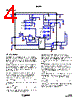
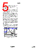
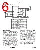
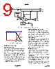
6 / 12 page  6 FN6435.0 February 25, 2008 Typical Application Circuit Theory of Operation When a valid input voltage is applied at VIN, the ISL9301 first regulates VOUT at 4.5V for system power need. In the mean time, if the battery is attached, the ISL9301 also charges the battery while supplying current to the system. When the system exceeds the maximum available current, either limited by the IC or by the input power supply, the charger FET is operated in a reverse mode, i.e. it discharges current to the system instead of charging. The charger function is similar to other Li-ion battery chargers, i.e. it charges the battery at a constant current (CC) or a constant voltage (CV) depending on the battery terminal voltage. The constant current IREF is set with the external resistor RIREF, as shown in the “Typical Application Circuit” on page 6. The constant voltage is fixed at 4.2V. If the battery voltage is below a typical 2.8V trickle charge threshold, the ISL9301 charges the battery with a trickle current (~16% of the programmed constant current) until the battery voltage rises above the trickle charge threshold. When the battery voltage reaches the final voltage of 4.2V, the charger enters the CV mode and regulates the battery voltage at 4.2V to fully charge the battery without the risk of overcharging. Upon reaching an end-of-charge (EOC) current, the charger indicates the charge completion with the CHG pin, but the charger continues to deliver 4.2V at the VBAT pin until the timeout limit has reached. Figure 1 shows the typical charge profile with the EOC/reset events. The EOC current level IMIN is programmable with the external resistor RIMIN. The CHG signal turns to LO when the trickle charge starts and rises to HIGH at an EOC event. After the EOC is reached, the CHG status is latched at HI. The CHG status will be reset to logic LO when the VBAT voltage drops to below the recharge threshold (4.05V), as shown in Figure 1. A thermal foldback function reduces the charge current anytime when the die temperature reaches typically +115°C. This function guarantees safe operation when the printed-circuit board (PCB) is not capable of dissipating the heat generated by the linear charger. ISL9301 VIN VBAT VOUT IREF IMIN CHG TIME TO SYS INPUT PPR RTIME RIMIN RIREF R1 R2 D2 D1 GND BATON TO μP PRESS AND HOLD 2s TO TURN ON C1 C2 C3 BATT R3 PART DESCRIPTION C1 10µF X5R ceramic cap C2 1µF X5R ceramic cap C3 4.7µF X5R ceramic cap R3 1 Ω, 5% resistor RIREF 26.7k Ω, 1%, for 150mA charge current RIMIN 137k Ω, 1%, for 23mA EOC current RTIME 1M Ω, 1% resistor for 75µs clock period R1, R2 470 Ω, 5% resistor D1, D2 LEDs for indication ISL9301 |
|
|
링크 URL |
| ALLDATASHEET 가 귀하에 도움이 되셨나요? [ DONATE ] |
Alldatasheet는? | 광고문의 | 운영자에게 연락하기 | 개인정보취급방침 | 링크 투 데이터시트 | 링크교환 | 제조사별 검색 All Rights Reserved©Alldatasheet.com |
| Russian : Alldatasheetru.com | Korean : Alldatasheet.co.kr | Spanish : Alldatasheet.es | French : Alldatasheet.fr | Italian : Alldatasheetit.com Portuguese : Alldatasheetpt.com | Polish : Alldatasheet.pl | Vietnamese : Alldatasheet.vn Indian : Alldatasheet.in | Mexican : Alldatasheet.com.mx | British : Alldatasheet.co.uk | New Zealand : Alldatasheet.co.nz |
|
Family Site : ic2ic.com |
icmetro.com |
 Korean ▼
 English
 Chinese
 German
 Japanese
 Russian
 Korean
 Spanish
 French
 Italian
 Portuguese
 Polish
 Vietnamese
 Indian
 Mexican
 British
 New Zealand