|
전자부품 데이터시트 검색엔진 |
|
|
전자부품 데이터시트 검색엔진 |
|
ISL9301 데이터시트(PDF) 8 Page - Intersil Corporation |
|
|
|||||||||||||||||||||||||||||
ISL9301 데이터시트(HTML) 8 Page - Intersil Corporation |
|
|
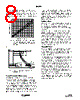
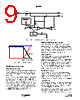
8 / 12 page  8 FN6435.0 February 25, 2008 when IREF is set to 145mA is shown in Figure 2. Figure 3 shows a typical time domain charge current curve vs time and its accuracy limits for a complete cycle. The accuracy is compared against the voltage on the IREF pin. Thermal foldback may affect the charge current curve as well as the accuracy. . Dynamic Power Path Management The power path management function of the ISL9301 controls the charge current and the system current when charging with system load. This is based on the available input current, which is either limited by the IC (800mA) or by the input power source, whichever is smaller. When the output voltage drops to the DPPM threshold (4.35V typical), the dynamic power path management starts to function. The DPPM control will first allocate the available current to the system load, using the remaining current to charge the battery. This is achieved by dynamically reducing the charge current until VOUT is regulated. In the event that the system needs more than the available current, VOUT will continue to drop. When VOUT drops to below the battery voltage, the DPPM control will turn on the charge control FET, allowing the battery to supply current to the system load. Thus the battery may be charged at a current smaller than the programmed constant current. Intelligent Timer The internal timer in the ISL9301 provides a time reference for the maximum charge time limit. The nominal clock cycle for the reference time is set by the external resistor connected between the TIME pin and GND and is given by Equation 1. The nominal maximum charge time interval is calculated based on the assumption that the programmed charge current is always available during the entire charging cycle. However, due to the PPM control or due to the current limit of the input source, or thermal foldback, the actual charge current maybe reduced during the constant current charge period. Under such conditions, the Intelligent Timer control will increase the timeout interval accordingly to allow approximately the same mAh product as the original timeout interval at the programmed current. Thermal Foldback The thermal foldback function starts to reduce the charge current when the internal temperature reaches a typical value of +115°C. When thermal foldback is encountered, the charge current will be reduced to a value where the die temperature stops rising. Figure 5 shows the thermal foldback operation whereas the current signals at the summing node of the current error amplifier CA are shown in Figure 4. IR is the reference. IT is the temperature tracking current generated from the Temperature Monitoring block. The IT has no impact on the charge current until the internal temperature reaches approximately +115°C; then IT starts to rise. In the mean time, as IT rises, ISEN will fall at the same rate (as the sum is a constant current IR). As a result, the charging current, which is proportional to ISEN, also decreases, keeping the die temperature constant at +115°C. The system output current, however, is not impacted by the thermal foldback. Thus, when the charge current is reduced to zero, if the die temperature still rises, the IC will shut down to prevent damage to the IC. 1.2 0 150 IR EF PIN VO L T A G E ( V ) FIGURE 2. IREF PIN VOLTAGE vs CHARGE CURRERNT (IREF IS SET TO 150mA. THE DOTTED LINES SHOW THE UPPER AND LOWER LIMITS OF THE TOLERANCE) IREF 1.1IREF 0.9IREF 0.16IREF 0.22IREF 0.12IREF ICHG TIME TRICKLE CC CV 1.3IMIN 1.0IMIN 0.7IMIN FIGURE 3. CHARGE CURRENT ACCURACY WHEN IREF = 145mA ISL9301 |
|
|
링크 URL |
| ALLDATASHEET 가 귀하에 도움이 되셨나요? [ DONATE ] |
Alldatasheet는? | 광고문의 | 운영자에게 연락하기 | 개인정보취급방침 | 링크 투 데이터시트 | 링크교환 | 제조사별 검색 All Rights Reserved©Alldatasheet.com |
| Russian : Alldatasheetru.com | Korean : Alldatasheet.co.kr | Spanish : Alldatasheet.es | French : Alldatasheet.fr | Italian : Alldatasheetit.com Portuguese : Alldatasheetpt.com | Polish : Alldatasheet.pl | Vietnamese : Alldatasheet.vn Indian : Alldatasheet.in | Mexican : Alldatasheet.com.mx | British : Alldatasheet.co.uk | New Zealand : Alldatasheet.co.nz |
|
Family Site : ic2ic.com |
icmetro.com |
 Korean ▼
 English
 Chinese
 German
 Japanese
 Russian
 Korean
 Spanish
 French
 Italian
 Portuguese
 Polish
 Vietnamese
 Indian
 Mexican
 British
 New Zealand