|
전자부품 데이터시트 검색엔진 |
|
|
전자부품 데이터시트 검색엔진 |
|
EM62100AGH 데이터시트(PDF) 49 Page - ELAN Microelectronics Corp |
|
|
|||||||||||||||||||||||||||||
EM62100AGH 데이터시트(HTML) 49 Page - ELAN Microelectronics Corp |
|
|
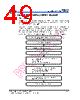
49 / 60 page  EM62100 65 COM/132 SEG STN LCD Driver Product Specification (V1.1) 09.13.2005 •••• 43 (This specification is subject to change without further notice) 7.3 Chip Initial State and Power ON/OFF Flowchart: 7.3.1 Initialization Note: For this chip, when power is applied, the LCD driving non-selective potentials V2 and V3 (segment pins) and V1 and V4 (common pins) are output through the LCD driving output pins SEG. and COM. When electric charge still remains in the smoothing capacitor connecting between the LCD driving voltage output pins (V0 - V4) and the VDD pin, the picture on the display may instantaneously become totally dark when power is turned on. To avoid such failure, we recommend the following flow sequence upon turning on the power. 7.3.1.1 With instant built-in power supply circuit, after turning on the power Turn ON the V DD - VSS power, keeping the RESB pin = "L" When power is stabilized Release the reset state (RESB pin = "H") Initialized state (Default) Function setup by command input (User setup) (11) LCD bias setting ( 8) ADC selection (15) Common output state selection Function setup by command input (User setup) (17) Setting the built-in resistance radio to regulate the V0 voltage (18) Electronic volume control Function setup by command input (User setup) (16) Power control setting This concludes the initialization |
|
링크 URL |
| ALLDATASHEET 가 귀하에 도움이 되셨나요? [ DONATE ] |
Alldatasheet는? | 광고문의 | 운영자에게 연락하기 | 개인정보취급방침 | 링크 투 데이터시트 | 링크교환 | 제조사별 검색 All Rights Reserved©Alldatasheet.com |
| Russian : Alldatasheetru.com | Korean : Alldatasheet.co.kr | Spanish : Alldatasheet.es | French : Alldatasheet.fr | Italian : Alldatasheetit.com Portuguese : Alldatasheetpt.com | Polish : Alldatasheet.pl | Vietnamese : Alldatasheet.vn Indian : Alldatasheet.in | Mexican : Alldatasheet.com.mx | British : Alldatasheet.co.uk | New Zealand : Alldatasheet.co.nz |
|
Family Site : ic2ic.com |
icmetro.com |
 Korean ▼
 English
 Chinese
 German
 Japanese
 Russian
 Korean
 Spanish
 French
 Italian
 Portuguese
 Polish
 Vietnamese
 Indian
 Mexican
 British
 New Zealand