|
전자부품 데이터시트 검색엔진 |
|
|
전자부품 데이터시트 검색엔진 |
|
AD8335 데이터시트(PDF) 16 Page - Analog Devices |
|
|
|||||||||||||||||||||||||||||
AD8335 데이터시트(HTML) 16 Page - Analog Devices |
|
|
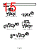
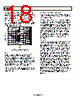
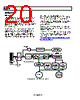
16 / 24 page  AD8335 Rev. 0 | Page 16 of 24 THEORY OF OPERATION Figure 54 is a simplified block diagram of a single channel. Each channel consists of a low noise preamplifier (PrA) followed by a VGA with a user-selectable gain of 20 dB or 28 dB. Channels are enabled in pairs, Channels 1 and 2 and Channels 3 and 4. The preamps are enabled by grounding Pins SPxx and powered down by connecting them to the positive supply. The ENxx pins are connected to the positive supply to enable the VGAs and the overall channel. HILO configures VGA for a fixed gain of 20 dB or 28 dB, with 0 V or 5 V applied to the HLxx pins, respectively. Channels 1 and 2 share Pin HL12, and Channels 3 and 4 share Pin HL34. The HLxx pins are typically hardwired to adjust the VGA gain according to an ADC resolution of 12 bits for LO gain and 10 bits for HI gain. The signal path is fully differential throughout to maximize signal swing and reduce even-order distortion; however, the preamplifiers are designed to be driven from a single-ended signal source. Gain values are referenced from the single-ended PrA input to the differential output of either the PrA or the VGA. Again referring to Figure 54, the system gain is distributed as listed in Table 4. Table 4. Channel Gain Distribution Section LO Nominal Gain (dB) HI Nominal Gain (dB) PrA 18.06 18.06 Attenuator 0 to −48.16 0 to −48.16 Output Amp 20 27.96 Aggregate −10.1 to +38.6 −2.14 to +46.02 In the remainder of this document, the gain values are rounded to −10 dB to +38 dB for LO gain mode and to −2 dB to +46 dB for HI gain mode. If desired, Equation 1 can be used to calculate the gain at value of VGAIN: ICPT V V dB dB Gain GN + = 20 ) ( (1) where ICPT = −16.1 dB for LO gain mode with the preamp input matched to 50 Ω (RFB = 250 Ω) and −10.1 dB for the unmatched input case. For HI gain mode, these numbers are −8.1 dB and −2.1 dB, respectively. Power consumption is 95 mW/channel from a 5 V supply, or 380 mW for all four channels. Power is distributed 35% for the PrA, and 65% for the remainder of the circuit. The preamps can be shut down via the SP12 and SP34 pins if a user wants to use the VGAs only. However, to avoid feedthrough around the preamp, feedback resistors should not be installed. ENABLE SUMMARY Table 5 summarizes the enable/shutdown logic and resulting supply current. Table 5. Control Pin Logic and Power Consumption EN12 SP12 EN34 SP34 PrA12 VGA12 PrA34 VGA34 IS H L H L On On On On 76 mA H H H H Off On Off On 52 mA L L L L Off Off Off Off 0.8 mA L H L H Off Off Off Off 0.8 mA +1 +1 +1 +1 PrA 18dB HILO +1 INTERPOLATOR ATTENx –48dB TO 0dB GAIN INTERFACE +1 BIAS OUTPUT AMP 20dB TO 28dB VOHx VOLx HLxx SLxx VGNx VCMx VIPx POPx ENxx PMDx PIPx PONx VINx RFB RS Figure 54. Simplified Block Diagram of Single Channel |
|
|
링크 URL |
| ALLDATASHEET 가 귀하에 도움이 되셨나요? [ DONATE ] |
Alldatasheet는? | 광고문의 | 운영자에게 연락하기 | 개인정보취급방침 | 링크 투 데이터시트 | 링크교환 | 제조사별 검색 All Rights Reserved©Alldatasheet.com |
| Russian : Alldatasheetru.com | Korean : Alldatasheet.co.kr | Spanish : Alldatasheet.es | French : Alldatasheet.fr | Italian : Alldatasheetit.com Portuguese : Alldatasheetpt.com | Polish : Alldatasheet.pl | Vietnamese : Alldatasheet.vn Indian : Alldatasheet.in | Mexican : Alldatasheet.com.mx | British : Alldatasheet.co.uk | New Zealand : Alldatasheet.co.nz |
|
Family Site : ic2ic.com |
icmetro.com |
 Korean ▼
 English
 Chinese
 German
 Japanese
 Russian
 Korean
 Spanish
 French
 Italian
 Portuguese
 Polish
 Vietnamese
 Indian
 Mexican
 British
 New Zealand