|
전자부품 데이터시트 검색엔진 |
|
|
전자부품 데이터시트 검색엔진 |
|
AD8335 데이터시트(PDF) 20 Page - Analog Devices |
|
|
|||||||||||||||||||||||||||||
AD8335 데이터시트(HTML) 20 Page - Analog Devices |
|
|
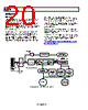
20 / 24 page  AD8335 Rev. 0 | Page 20 of 24 APPLICATIONS ULTRASOUND The primary application for the AD8335 is medical ultrasound. Figure 57 shows a simplified block diagram of an ultrasound system. The most critical function of an ultrasound system is the time gain control (TGC) compensation for physiological signal attenuation. Because the attenuation of ultrasound signals is exponential with respect to distance (time), a linear-in-dB VGA is the optimal solution. Key requirements in an ultrasound signal chain are very low noise, active input termination, fast overload recovery, low power, and differential drive to an ADC. Because ultrasound machines use beamforming techniques requiring large binary weighted numbers (for example, 32 to 512) of channels, the lowest power at the lowest possible noise is of key importance. Most modern machines use digital beamforming. In this technique, the signal is converted to digital format immediately following the TGC amplifier; beamforming is done digitally. Typical ADC resolution in general purpose machines is 10 bits with sampling rates greater than 40 MSPS, while high end systems use 12 bits. Power consumption and low cost are of primary importance in low-end and portable ultrasound machines, and the AD8335 is designed for these criteria. For additional information regarding ultrasound systems, refer to “How Ultrasound System Considerations Influence Front- End Component Choice”, Analog Dialogue, Vol. 36, No. 3, May–July 2003. (http://www.analog.com/library/analogDialogue/archives/36- 03/ultrasound/index.html) BEAMFORMER CENTRAL CONTROL Rx BEAMFORMER (B AND F MODES) COLOR DOPPLER (PW) PROCESSING (F MODE) IMAGE AND MOTION PROCESSING (B MODE) SPECTRAL DOPPLER PROCESSING MODE DISPLAY AUDIO OUTPUT TX BEAMFORMER CW (ANALOG) BEAMFORMER LNAs TRANSDUCER ARRAY 128, 256 ETC. ELEMENTS BIDIRECTIONAL CABLE HV MUX/ DEMUX T/R SWITCHES TX HV AMPs MULTICHANNEL TGC USES MANY VGAs TGC TIME GAIN COMPENSATION VGAs AD8335 Figure 57. Simplified Ultrasound System Block Diagram |
|
|
링크 URL |
| ALLDATASHEET 가 귀하에 도움이 되셨나요? [ DONATE ] |
Alldatasheet는? | 광고문의 | 운영자에게 연락하기 | 개인정보취급방침 | 링크 투 데이터시트 | 링크교환 | 제조사별 검색 All Rights Reserved©Alldatasheet.com |
| Russian : Alldatasheetru.com | Korean : Alldatasheet.co.kr | Spanish : Alldatasheet.es | French : Alldatasheet.fr | Italian : Alldatasheetit.com Portuguese : Alldatasheetpt.com | Polish : Alldatasheet.pl | Vietnamese : Alldatasheet.vn Indian : Alldatasheet.in | Mexican : Alldatasheet.com.mx | British : Alldatasheet.co.uk | New Zealand : Alldatasheet.co.nz |
|
Family Site : ic2ic.com |
icmetro.com |
 Korean ▼
 English
 Chinese
 German
 Japanese
 Russian
 Korean
 Spanish
 French
 Italian
 Portuguese
 Polish
 Vietnamese
 Indian
 Mexican
 British
 New Zealand