|
전자부품 데이터시트 검색엔진 |
|
|
전자부품 데이터시트 검색엔진 |
|
AFE4490 데이터시트(PDF) 5 Page - Texas Instruments |
|
|
|
|||||||||||||||||||||||||||||
AFE4490 데이터시트(HTML) 5 Page - Texas Instruments |
|
|
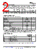
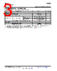
5 / 69 page  AFE4400 www.ti.com SBAS601D – DECEMBER 2012 – REVISED MAY 2013 ELECTRICAL CHARACTERISTICS (continued) Minimum and maximum specifications are at TA = –20°C to +85°C. Typical specifications are at +25°C. All specifications are at RX_ANA_SUP = RX_DIG_SUP = 3 V, TX_CTRL_SUP = LED_DRV_SUP = 3.3 V, and fCLK = 8 MHz, unless otherwise noted. PARAMETER TEST CONDITIONS MIN TYP MAX UNIT AMBIENT CANCELLATION STAGE Gain 1, 1.414, 2, 2.828, and 4 V/V Current DAC range 0 10 µA Current DAC step size 1 µA LOW-PASS FILTER Low-pass corner frequency 3-dB attenuation 500 Hz Duty cycle = 25% 0.004 dB Pass-band attenuation, 2 Hz to 10 Hz Duty cycle = 10% 0.041 dB ANALOG-TO-DIGITAL CONVERTER Resolution 22 Bits See the ADC Operation and Averaging Sample rate 4 × PRF SPS Module section ADC full-scale voltage ±1.2 V See the ADC Operation and Averaging ADC conversion time 50 PRF / 4 µs Module section ADC reset time 2 tCLK TRANSMITTER Selectable, 0 to 50 Output current range (see the LEDCNTRL: LED Control mA Register for details) LED current DAC error ±10% Output current resolution 8 Bits At 5-mA output current 95 dB Transmitter noise dynamic range, At 25-mA output current 95 dB over 0.1-Hz to 5-Hz bandwidth At 50-mA output current 95 dB At 50-mA output current, 1.4 + (voltage drop across LED, V H-bridge LED driver configuration cable, and so forth) to 5.25 Voltage on TXP (or TXM) pin when low-side switch connected to TXP (or TXM) turns on At 50-mA output current, 1.3 + (voltage drop across LED, V common anode LED driver configuration cable, and so forth) to 5.25 Minimum sample time of LED1 and LED2 50 µs pulses LED_ON = 0 1 µA LED current DAC leakage current LED_ON = 1 50 µA LED current DAC linearity Percent of full-scale current 0.5% From zero current to 50 mA 7 µs Output current settling time (with resistive load) From 50 mA to zero current 7 µs DIAGNOSTICS Start of diagnostics after the DIAG_EN 4k cycles register bit is set. Duration of diagnostics state machine 16 of 4-MHz End of diagnostic is indicated by DIAG_END clock going high. Open fault resistance > 100 k Ω Short fault resistance < 10 k Ω INTERNAL OSCILLATOR With an 8-MHz crystal connected to the XIN, fCLKOUT CLKOUT frequency 4 MHz XOUT pins CLKOUT duty cycle 50% With an 8-MHz crystal connected to the XIN, Crystal oscillator start-up time 200 µs XOUT pins Copyright © 2012–2013, Texas Instruments Incorporated Submit Documentation Feedback 5 Product Folder Links: AFE4400 |
|
링크 URL |
| ALLDATASHEET 가 귀하에 도움이 되셨나요? [ DONATE ] |
Alldatasheet는? | 광고문의 | 운영자에게 연락하기 | 개인정보취급방침 | 링크 투 데이터시트 | 링크교환 | 제조사별 검색 All Rights Reserved©Alldatasheet.com |
| Russian : Alldatasheetru.com | Korean : Alldatasheet.co.kr | Spanish : Alldatasheet.es | French : Alldatasheet.fr | Italian : Alldatasheetit.com Portuguese : Alldatasheetpt.com | Polish : Alldatasheet.pl | Vietnamese : Alldatasheet.vn Indian : Alldatasheet.in | Mexican : Alldatasheet.com.mx | British : Alldatasheet.co.uk | New Zealand : Alldatasheet.co.nz |
|
Family Site : ic2ic.com |
icmetro.com |
 Korean ▼
 English
 Chinese
 German
 Japanese
 Russian
 Korean
 Spanish
 French
 Italian
 Portuguese
 Polish
 Vietnamese
 Indian
 Mexican
 British
 New Zealand