|
전자부품 데이터시트 검색엔진 |
|
|
전자부품 데이터시트 검색엔진 |
|
AFE4490 데이터시트(PDF) 2 Page - Texas Instruments |
|
|
|
|||||||||||||||||||||||||||||
AFE4490 데이터시트(HTML) 2 Page - Texas Instruments |
|
|
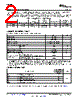
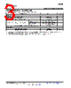
2 / 69 page  AFE4400 SBAS601D – DECEMBER 2012 – REVISED MAY 2013 www.ti.com This integrated circuit can be damaged by ESD. Texas Instruments recommends that all integrated circuits be handled with appropriate precautions. Failure to observe proper handling and installation procedures can cause damage. ESD damage can range from subtle performance degradation to complete device failure. Precision integrated circuits may be more susceptible to damage because very small parametric changes could cause the device not to meet its published specifications. FAMILY AND ORDERING INFORMATION LED DRIVE OPERATING LED DRIVE CURRENT POWER SUPPLY TEMPERATURE PRODUCT PACKAGE-LEAD CONFIGURATION (mA, max) (V) RANGE AFE4400 QFN-40 Bridge, push-pull 50 3 to 3.6 0°C to +70°C 50, 75, 100, AFE4490 QFN-40 Bridge, push-pull 3 to 5.25 –40°C to +85°C 150, and 200 ABSOLUTE MAXIMUM RATINGS (1) Over operating free-air temperature range, unless otherwise noted. VALUE UNIT AVDD to AVSS –0.3 to +7 V DVDD to DGND –0.3 to +7 V AGND to DGND –0.3 to +0.3 V Analog input to AVSS AVSS – 0.3 to AVDD + 0.3 V Digital input to DVDD DVSS – 0.3 to DVDD + 0.3 V Input current to any pin except supply pins(2) ±7 mA Momentary ±50 mA Input current Continuous ±7 mA Operating temperature range 0 to +70 °C Storage temperature range, Tstg –60 to +150 °C Maximum junction temperature, TJ +125 °C Human body model (HBM) ±4000 V JEDEC standard 22, test method A114-C.01, all pins Electrostatic discharge (ESD) ratings Charged device model (CDM) ±1500 V JEDEC standard 22, test method C101, all pins (1) Stresses beyond those listed under Absolute Maximum Ratings may cause permanent damage to the device. These are stress ratings only, and do not imply functional operation of the device at these or any other conditions beyond those indicated under Recommended Operating Conditions. Exposure to absolute-maximum-rated conditions for extended periods may affect device reliability. (2) Input terminals are diode-clamped to the power-supply rails. Input signals that can swing beyond the supply rails must be current-limited to 10 mA or less. THERMAL INFORMATION AFE4400 THERMAL METRIC(1) RHA (QFN) UNITS 40 PINS θJA Junction-to-ambient thermal resistance 35 θJCtop Junction-to-case (top) thermal resistance 31 θJB Junction-to-board thermal resistance 26 °C/W ψJT Junction-to-top characterization parameter 0.1 ψJB Junction-to-board characterization parameter n/a θJCbot Junction-to-case (bottom) thermal resistance n/a (1) For more information about traditional and new thermal metrics, see the IC Package Thermal Metrics application report, SPRA953. 2 Submit Documentation Feedback Copyright © 2012–2013, Texas Instruments Incorporated Product Folder Links: AFE4400 |
|
링크 URL |
| ALLDATASHEET 가 귀하에 도움이 되셨나요? [ DONATE ] |
Alldatasheet는? | 광고문의 | 운영자에게 연락하기 | 개인정보취급방침 | 링크 투 데이터시트 | 링크교환 | 제조사별 검색 All Rights Reserved©Alldatasheet.com |
| Russian : Alldatasheetru.com | Korean : Alldatasheet.co.kr | Spanish : Alldatasheet.es | French : Alldatasheet.fr | Italian : Alldatasheetit.com Portuguese : Alldatasheetpt.com | Polish : Alldatasheet.pl | Vietnamese : Alldatasheet.vn Indian : Alldatasheet.in | Mexican : Alldatasheet.com.mx | British : Alldatasheet.co.uk | New Zealand : Alldatasheet.co.nz |
|
Family Site : ic2ic.com |
icmetro.com |
 Korean ▼
 English
 Chinese
 German
 Japanese
 Russian
 Korean
 Spanish
 French
 Italian
 Portuguese
 Polish
 Vietnamese
 Indian
 Mexican
 British
 New Zealand