|
전자부품 데이터시트 검색엔진 |
|
|
전자부품 데이터시트 검색엔진 |
|
MPC8309EC 데이터시트(PDF) 76 Page - Freescale Semiconductor, Inc |
|
|
|||||||||||||||||||||||||||||
MPC8309EC 데이터시트(HTML) 76 Page - Freescale Semiconductor, Inc |
|
|
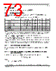
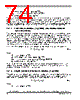
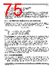
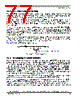
76 / 82 page  MPC8309 PowerQUICC II Pro Integrated Communications Processor Family Hardware Specifications, Rev. 0 76 Freescale Semiconductor System Design Information lifetime of the package. Recommended maximum force on the top of the package is 10 lb (4.5 kg) force. If an adhesive attachment is planned, the adhesive should be intended for attachment to painted or plastic surfaces and its performance verified under the application requirements. 24.2.1 Experimental Determination of the Junction Temperature with a Heat Sink When heat sink is used, the junction temperature is determined from a thermocouple inserted at the interface between the case of the package and the interface material. A clearance slot or hole is normally required in the heat sink. Minimizing the size of the clearance is important to minimize the change in thermal performance caused by removing part of the thermal interface to the heat sink. Because of the experimental difficulties with this technique, many engineers measure the heat sink temperature and then back calculate the case temperature using a separate measurement of the thermal resistance of the interface. From this case temperature, the junction temperature is determined from the junction-to-case thermal resistance using the following equation: TJ = TC +(RJC PD) Eqn. 5 where: TC = case temperature of the package (C) RJC = junction-to-case thermal resistance (C/W) PD = power dissipation (W) 25 System Design Information This section provides electrical and thermal design recommendations for successful application of the MPC8309. 25.1 System Clocking The MPC8309 includes three PLLs. • The system PLL (AVDD2) generates the system clock from the externally supplied SYS_CLK_IN input. The frequency ratio between the system and SYS_CLK_IN is selected using the system PLL ratio configuration bits as described in Section 23.4, “System PLL Configuration.” • The e300 core PLL (AVDD3) generates the core clock as a slave to the system clock. The frequency ratio between the e300 core clock and the system clock is selected using the e300 PLL ratio configuration bits as described in Section 23.5, “Core PLL Configuration.” • The QUICC Engine PLL (AVDD1) which uses the same reference as the system PLL. The QUICC Engine block generates or uses external sources for all required serial interface clocks. |
|
링크 URL |
| ALLDATASHEET 가 귀하에 도움이 되셨나요? [ DONATE ] |
Alldatasheet는? | 광고문의 | 운영자에게 연락하기 | 개인정보취급방침 | 링크 투 데이터시트 | 링크교환 | 제조사별 검색 All Rights Reserved©Alldatasheet.com |
| Russian : Alldatasheetru.com | Korean : Alldatasheet.co.kr | Spanish : Alldatasheet.es | French : Alldatasheet.fr | Italian : Alldatasheetit.com Portuguese : Alldatasheetpt.com | Polish : Alldatasheet.pl | Vietnamese : Alldatasheet.vn Indian : Alldatasheet.in | Mexican : Alldatasheet.com.mx | British : Alldatasheet.co.uk | New Zealand : Alldatasheet.co.nz |
|
Family Site : ic2ic.com |
icmetro.com |
 Korean ▼
 English
 Chinese
 German
 Japanese
 Russian
 Korean
 Spanish
 French
 Italian
 Portuguese
 Polish
 Vietnamese
 Indian
 Mexican
 British
 New Zealand