|
전자부품 데이터시트 검색엔진 |
|
|
전자부품 데이터시트 검색엔진 |
|
MPC8309EC 데이터시트(PDF) 78 Page - Freescale Semiconductor, Inc |
|
|
|||||||||||||||||||||||||||||
MPC8309EC 데이터시트(HTML) 78 Page - Freescale Semiconductor, Inc |
|
|
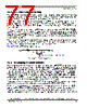
78 / 82 page  MPC8309 PowerQUICC II Pro Integrated Communications Processor Family Hardware Specifications, Rev. 0 78 Freescale Semiconductor System Design Information to minimize inductance. Suggested bulk capacitors—100 to 330 µF (AVX TPS tantalum or Sanyo OSCON). 25.4 Output Buffer DC Impedance For all buses, the driver is a push-pull single-ended driver type (open drain for I2C). To measure Z0 for the single-ended drivers, an external resistor is connected from the chip pad to OVDD or GND. Then, the value of each resistor is varied until the pad voltage is OVDD/2 (see Figure 47). The output impedance is the average of two components, the resistances of the pull-up and pull-down devices. When data is held high, SW1 is closed (SW2 is open) and RP is trimmed until the voltage at the pad equals OVDD/2. RP then becomes the resistance of the pull-up devices. RP and RN are designed to be close to each other in value. Then, Z0 =(RP +RN)/2. Figure 47. Driver Impedance Measurement The value of this resistance and the strength of the driver’s current source can be found by making two measurements. First, the output voltage is measured while driving logic 1 without an external differential termination resistor. The measured voltage is V1 = Rsource Isource. Second, the output voltage is measured while driving logic 1 with an external precision differential termination resistor of value Rterm. The measured voltage is V2 =(1/(1/R1 +1/R2)) Isource. Solving for the output impedance gives Rsource =Rterm (V1/V2 – 1). The drive current is then Isource =V1/Rsource. OVDD OGND RP RN Pad Data SW1 SW2 |
|
링크 URL |
| ALLDATASHEET 가 귀하에 도움이 되셨나요? [ DONATE ] |
Alldatasheet는? | 광고문의 | 운영자에게 연락하기 | 개인정보취급방침 | 링크 투 데이터시트 | 링크교환 | 제조사별 검색 All Rights Reserved©Alldatasheet.com |
| Russian : Alldatasheetru.com | Korean : Alldatasheet.co.kr | Spanish : Alldatasheet.es | French : Alldatasheet.fr | Italian : Alldatasheetit.com Portuguese : Alldatasheetpt.com | Polish : Alldatasheet.pl | Vietnamese : Alldatasheet.vn Indian : Alldatasheet.in | Mexican : Alldatasheet.com.mx | British : Alldatasheet.co.uk | New Zealand : Alldatasheet.co.nz |
|
Family Site : ic2ic.com |
icmetro.com |
 Korean ▼
 English
 Chinese
 German
 Japanese
 Russian
 Korean
 Spanish
 French
 Italian
 Portuguese
 Polish
 Vietnamese
 Indian
 Mexican
 British
 New Zealand