|
전자부품 데이터시트 검색엔진 |
|
|
전자부품 데이터시트 검색엔진 |
|
MPC8309EC 데이터시트(PDF) 14 Page - Freescale Semiconductor, Inc |
|
|
|||||||||||||||||||||||||||||
MPC8309EC 데이터시트(HTML) 14 Page - Freescale Semiconductor, Inc |
|
|
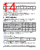
14 / 82 page  MPC8309 PowerQUICC II Pro Integrated Communications Processor Family Hardware Specifications, Rev. 0 14 Freescale Semiconductor RESET Initialization 5 RESET Initialization This section describes the AC electrical specifications for the reset initialization timing requirements of the MPC8309. Table 9 provides the reset initialization AC timing specifications for the reset component(s). Table 10 provides the PLL lock times. 5.1 Reset Signals DC Electrical Characteristics Table 11 provides the DC electrical characteristics for the MPC8309 reset signals mentioned in Table 9. SYS_CLK_IN duty cycle tKHK/tSYS_CLK_ IN 40 — 60 % 3 SYS_CLK_IN jitter — — — ±150 ps 4, 5 Notes: 1. Caution: The system, core and QUICC Engine block must not exceed their respective maximum or minimum operating frequencies. 2. Rise and fall times for SYS_CLK_IN are measured at 0.33 and 2.97 V. 3. Timing is guaranteed by design and characterization. 4. This represents the total input jitter—short term and long term—and is guaranteed by design. 5. The SYS_CLK_IN driver’s closed loop jitter bandwidth should be < 500 kHz at –20 dB. The bandwidth must be set low to allow cascade-connected PLL-based devices to track SYS_CLK_IN drivers with the specified jitter. 6. Spread spectrum is allowed upto 1% down-spread @ 33kHz (max rate). Table 9. RESET Initialization Timing Specifications Parameter/Condition Min Max Unit Notes Required assertion time of HRESET to activate reset flow 32 — tSYS_CLK_IN 1 Required assertion time of PORESET with stable clock applied to SYS_CLK_IN or PCI_SYNC_IN (in agent mode) 32 — tSYS_CLK_IN 1 HRESET assertion (output) 512 — tSYS_CLK_IN 1 Input setup time for POR configuration signals (CFG_RESET_SOURCE[0:3]) with respect to negation of PORESET 4— tSYS_CLK_IN 1, 2 Input hold time for POR config signals with respect to negation of HRESET 0 — ns 1, 2 Notes: 1. tSYS_CLK_IN is the clock period of the input clock applied to SYS_CLK_IN. For more details, see the MPC8309 PowerQUICC II Pro Integrated Communications Processor Reference Manual. 2. POR configuration signals consists of CFG_RESET_SOURCE[0:3]. Table 10. PLL Lock Times Parameter/Condition Min Max Unit Notes PLL lock times — 100 s— Table 8. SYS_CLK_IN AC Timing Specifications |
|
링크 URL |
| ALLDATASHEET 가 귀하에 도움이 되셨나요? [ DONATE ] |
Alldatasheet는? | 광고문의 | 운영자에게 연락하기 | 개인정보취급방침 | 링크 투 데이터시트 | 링크교환 | 제조사별 검색 All Rights Reserved©Alldatasheet.com |
| Russian : Alldatasheetru.com | Korean : Alldatasheet.co.kr | Spanish : Alldatasheet.es | French : Alldatasheet.fr | Italian : Alldatasheetit.com Portuguese : Alldatasheetpt.com | Polish : Alldatasheet.pl | Vietnamese : Alldatasheet.vn Indian : Alldatasheet.in | Mexican : Alldatasheet.com.mx | British : Alldatasheet.co.uk | New Zealand : Alldatasheet.co.nz |
|
Family Site : ic2ic.com |
icmetro.com |
 Korean ▼
 English
 Chinese
 German
 Japanese
 Russian
 Korean
 Spanish
 French
 Italian
 Portuguese
 Polish
 Vietnamese
 Indian
 Mexican
 British
 New Zealand