|
전자부품 데이터시트 검색엔진 |
|
|
전자부품 데이터시트 검색엔진 |
|
COP8SE 데이터시트(PDF) 12 Page - National Semiconductor (TI) |
|
|
|
|||||||||||||||||||||||||||||
COP8SE 데이터시트(HTML) 12 Page - National Semiconductor (TI) |
|
|
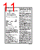
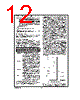
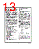
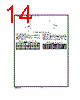
12 / 47 page  5.0 Functional Description (Continued) Caution: In order to prevent the unexpected setting of the ILRW of the E2CFG Register and the corresponding interrupt, the use of the X Register and direct addressing are recommanded for EERAM ac- cess. It is further recommended that the B Register be set to a value between 80 (hex) and FF (hex) before setting the Segment register to 1 and that this value be retained until S is set back to 0. Due to an artifact of the COP8 architecture, the ILRW bit of the E2CFG Register will be set and an interrupt will be generated un- der the following conditions: 1. The Segment Register (S) = 01, and 2. The B Register points to the EERAM, i.e. B ≤7F (hex), and 3. One of the following instructions is executed: SC, RC, IFC, IFNC, NOP, RPND, SWAPA, JMPL, VIS or LD B, Imm with Imm ≤7F (hex), or 3a. if any instruction is skipped. Warning: The segment register should not point to the EE- RAM unless the EERAM is addressed. This will prevent in- advertent writes to EERAM. 5.4.1. E2CFG and EE Support Circuitry The EERAM module contains EERAM support circuits to generate all necessary high voltage programming pulses. The E2CFG register provides control and status functions for the EERAM module. The E2CFG register bit assignments are shown below. The E2CFG register is set to 0 on RESET except the E2BUSY bit, which is unaffected. The EECFG register can be accessed at any time without error. Reserved, must be 0 E2PEND E2ILRW E2BUSY E2EI R/W R/W R/W R/W R/W R/W RO R/W Bit 7 Bit 0 RESERVED These bits are reserved and must be 0. E2PEND Interrupt Pending Bit. This bit indicates that a write operation has completed and a Write Complete Interrupt is pending. This bit is logically ANDed with the E2EI bit to cause an interrupt. This bit can be written by either hardware or software. This bit must be reset by software after processing the interrupt. E2ILRW EERAM illegal read/write operation. This bit is set when the EERAM array is accessed while E2BUSY is set. This bit will cause an EERAM interrupt, without setting the E2PEND bit, if the E2EI bit is set. This bit can be written by either hardware or soft- ware. This bit must be reset by software af- ter processing the interrupt. E2BUSY This bit is set by the hardware when a write to the EERAM is in process and reset by the hardware when the write completes. The E2PEND bit is set when this bit is reset. This bit is software read-only. E2EI Interrupt Enable Bit. Setting this bit enables EERAM interrupts. The default condition is interrupts disabled after RESET. This bit must be used in conjunction with the GIE bit. This bit can be written by software only. 5.5 DATA MEMORY SEGMENT RAM EXTENSION Data memory address 0FF is used as a memory mapped lo- cation for the Data Segment Address Register (S). The data store memory is either addressed directly by a single byte address within the instruction, or indirectly rela- tive to the reference of the B, X, or SP pointers (each con- tains a single-byte address). This single-byte address allows an addressing range of 256 locations from 00 to FF hex. The upper bit of this single-byte address divides the data store memory into two separate sections as outlined previously. With the exception of the RAM register memory from ad- dress locations 00F0 to 00FF, all RAM memory is memory mapped with the upper bit of the single-byte address being equal to zero. This allows the upper bit of the single-byte ad- dress to determine whether or not the base address range (from 0000 to 00FF) is extended. If this upper bit equals one (representing address range 0080 to 00FF), then address extension does not take place. Alternatively, if this upper bit equals zero, then the data segment extension register S is used to extend the base address range (from 0000 to 007F) from XX00 to XX7F, where XX represents the 8 bits from the S register. Thus the 128-byte data segment extensions are located from addresses 0100 to 017F for data segment 1, 0200 to 027F for data segment 2, etc., up to FF00 to FF7F for data segment 255. The base address range from 0000 to 007F represents data segment 0. Figure 8 illustrates how the S register data memory exten- sion is used in extending the lower half of the base address range (00 to 7F hex) into 256 data segments of 128 bytes each, with a total addressing range of 32 kbytes from XX00 to XX7F. This organization allows a total of 256 data seg- ments of 128 bytes each with an additional upper base seg- ment of 128 bytes. Furthermore, all addressing modes are available for all data segments. The S register must be changed under program control to move from one data seg- ment (128 bytes) to another. However, the upper base seg- ment (containing the 16 memory registers, I/O registers, control registers, etc.) is always available regardless of the contents of the S register, since the upper base segment (address range 0080 to 00FF) is independent of data seg- ment extension. The instructions that utilize the stack pointer (SP) always ref- erence the stack as part of the base segment (Segment 0), regardless of the contents of the S register. The S register is DS100973-45 FIGURE 8. RAM Organization www.national.com 12 |
|
링크 URL |
| ALLDATASHEET 가 귀하에 도움이 되셨나요? [ DONATE ] |
Alldatasheet는? | 광고문의 | 운영자에게 연락하기 | 개인정보취급방침 | 링크 투 데이터시트 | 링크교환 | 제조사별 검색 All Rights Reserved©Alldatasheet.com |
| Russian : Alldatasheetru.com | Korean : Alldatasheet.co.kr | Spanish : Alldatasheet.es | French : Alldatasheet.fr | Italian : Alldatasheetit.com Portuguese : Alldatasheetpt.com | Polish : Alldatasheet.pl | Vietnamese : Alldatasheet.vn Indian : Alldatasheet.in | Mexican : Alldatasheet.com.mx | British : Alldatasheet.co.uk | New Zealand : Alldatasheet.co.nz |
|
Family Site : ic2ic.com |
icmetro.com |
 Korean ▼
 English
 Chinese
 German
 Japanese
 Russian
 Korean
 Spanish
 French
 Italian
 Portuguese
 Polish
 Vietnamese
 Indian
 Mexican
 British
 New Zealand