|
전자부품 데이터시트 검색엔진 |
|
|
전자부품 데이터시트 검색엔진 |
|
COP8SE 데이터시트(PDF) 19 Page - National Semiconductor (TI) |
|
|
|
|||||||||||||||||||||||||||||
COP8SE 데이터시트(HTML) 19 Page - National Semiconductor (TI) |
|
|
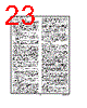
19 / 47 page  7.0 Power Saving Features Today, the proliferation of battery-operated based applica- tions has placed new demands on designers to drive power consumption down. Battery-operated systems are not the only type of applications demanding low power. The power budget constraints are also imposed on those consumer/ industrial applications where well regulated and expensive power supply costs cannot be tolerated. Such applications rely on low cost and low power supply voltage derived di- rectly from the “mains” by using voltage rectifier and passive components. Low power is demanded even in automotive applications, due to increased vehicle electronics content. This is required to ease the burden from the car battery. Low power 8-bit microcontrollers supply the smarts to control battery-operated, consumer/industrial, and automotive appli- cations. Each device offers system designers a variety of low-power consumption features that enable them to meet the demand- ing requirements of today’s increasing range of low-power applications. These features include low voltage operation, low current drain, and power saving features such as HALT, IDLE, and Multi-Input wakeup (MIWU). Each device offers the user two power save modes of opera- tion: HALT and IDLE. In the HALT mode, all microcontroller activities are stopped. In the IDLE mode, the on-board oscil- lator circuitry and timer T0 are active but all other microcon- troller activities are stopped. In either mode, all on-board RAM, registers, I/O states, and timers (with the exception of T0) are unaltered. Clock Monitor if enabled can be active in both modes. 7.1 HALT MODE Each device can be placed in the HALT mode by writing a “1” to the HALT flag (G7 data bit). All microcontroller activities, including the clock and timers, are stopped. The WATCH- DOG logic on the devices are disabled during the HALT mode. However, the clock monitor circuitry, if enabled, re- mains active and will cause the WATCHDOG output pin (WDOUT) to go low. If the HALT mode is used and the user does not want to activate the WDOUT pin, the Clock Monitor should be disabled after the devices come out of reset (re- setting the Clock Monitor control bit with the first write to the WDSVR register). In the HALT mode, the power require- ments of the devices are minimal and the applied voltage (V CC) may be decreased to Vr (Vr = 2.0V) without altering the state of the machine. Each device supports three different ways of exiting the HALT mode. The first method of exiting the HALT mode is with the Multi-Input Wakeup feature on Port L. The second method is with a low to high transition on the CKO (G7) pin. This method precludes the use of the crystal clock configura- tion (since CKO becomes a dedicated output), and so may only be used with an R/C clock configuration. The third method of exiting the HALT mode is by pulling the RESET pin low. On wakeup from G7 or Port L, the devices resume execution from the HALT point. On wakeup from RESET execution will resume from location PC=0 and all RESET conditions apply. If a crystal or ceramic resonator may be selected as the os- cillator, the Wakeup signal is not allowed to start the chip running immediately since crystal oscillators and ceramic resonators have a delayed start up time to reach full ampli- tude and frequency stability. The IDLE timer is used to gen- erate a fixed delay to ensure that the oscillator has indeed stabilized before allowing instruction execution. In this case, upon detecting a valid Wakeup signal, only the oscillator cir- cuitry is enabled. The IDLE timer is loaded with a value of 256 and is clocked with the t C instruction cycle clock. The tC clock is derived by dividing the oscillator clock down by a fac- tor of 9. The Schmitt trigger following the CKI inverter on the chip ensures that the IDLE timer is clocked only when the os- cillator has a sufficiently large amplitude to meet the Schmitt trigger specifications. This Schmitt trigger is not part of the oscillator closed loop. The start-up time-out from the IDLE timer enables the clock signals to be routed to the rest of the chip. If an R/C clock option is being used, the fixed delay is intro- duced optionally. A control bit, CLKDLY, mapped as configu- ration bit G7, controls whether the delay is to be introduced or not. The delay is included if CLKDLY is set, and excluded if CLKDLY is reset. The CLKDLY bit is cleared on reset. Each device has two options associated with the HALT mode. The first option enables the HALT mode feature, while the second option disables the HALT mode selected through bit 0 of the mask option. With the HALT mode enable option, the device will enter and exit the HALT mode as described above. With the HALT disable option, the device cannot be placed in the HALT mode (writing a “1” to the HALT flag will have no effect, the HALT flag will remain “0”). The WATCHDOG detector circuit is inhibited during the HALT mode. However, the clock monitor circuit if enabled re- mains active during HALT mode in order to ensure a clock monitor error if the device inadvertently enters the HALT mode as a result of a runaway program or power glitch. If the device is placed in the HALT mode, with the R/C oscil- lator selected, the clock input pin (CKI) is forced to a logic high internally. With the crystal oscillator the CKI pin is TRI-STATE. www.national.com 19 |
|
링크 URL |
| ALLDATASHEET 가 귀하에 도움이 되셨나요? [ DONATE ] |
Alldatasheet는? | 광고문의 | 운영자에게 연락하기 | 개인정보취급방침 | 링크 투 데이터시트 | 링크교환 | 제조사별 검색 All Rights Reserved©Alldatasheet.com |
| Russian : Alldatasheetru.com | Korean : Alldatasheet.co.kr | Spanish : Alldatasheet.es | French : Alldatasheet.fr | Italian : Alldatasheetit.com Portuguese : Alldatasheetpt.com | Polish : Alldatasheet.pl | Vietnamese : Alldatasheet.vn Indian : Alldatasheet.in | Mexican : Alldatasheet.com.mx | British : Alldatasheet.co.uk | New Zealand : Alldatasheet.co.nz |
|
Family Site : ic2ic.com |
icmetro.com |
 Korean ▼
 English
 Chinese
 German
 Japanese
 Russian
 Korean
 Spanish
 French
 Italian
 Portuguese
 Polish
 Vietnamese
 Indian
 Mexican
 British
 New Zealand