|
전자부품 데이터시트 검색엔진 |
|
|
전자부품 데이터시트 검색엔진 |
|
COP8SE 데이터시트(PDF) 20 Page - National Semiconductor (TI) |
|
|
|
|||||||||||||||||||||||||||||
COP8SE 데이터시트(HTML) 20 Page - National Semiconductor (TI) |
|
|
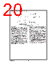
20 / 47 page  7.0 Power Saving Features (Continued) 7.2 IDLE MODE The device is placed in the IDLE mode by writing a ″1″ to the IDLE flag (G6 data bit). In this mode, all activity, except the associated on-board oscillator circuitry, the WATCHDOG logic, the clock monitor and the IDLE Timer T0, is stopped. The power supply requirements of the microcontroller in this mode of operation are typically around 30% of normal power requirement of the microcontroller. As with the HALT mode, the device can be returned to nor- mal operation with a reset, or with a Multi-Input Wakeup from the L Port. The microcontroller may also be awakened from the IDLE mode after a selectable amount of time up to 65,536 instruc- tion cycles, or 65.536 milliseconds with a 1 MHz instruction clock frequency (10 MHz oscillator). The IDLE timer period is selectable from one of five values, 4k, 8k, 16k, 32k or 64k instruction cycles. Selection of this value is made through the ITMR register. The user has the option of being interrupted with an under- flow of the selected bit of the IDLE Timer T0. This condition is latched into the T0PND pending flag. The interrupt can be enabled or disabled via the T0EN control bit. Setting the T0EN flag enables the interrupt and vice versa. The user can enter the IDLE mode with the Timer T0 inter- rupt enabled. In this case, when the T0PND bit gets set, the device will first execute the Timer T0 interrupt service routine and then return to the instruction following the ″Enter Idle Mode ″ instruction. Alternatively, the user can enter the IDLE mode with the IDLE Timer T0 interrupt disabled. In this case, the device will resume normal operation with the instruction immediately following the ″Enter IDLE Mode″ instruction. The IDLE timer cannot be started or stopped under software control, and it is not memory mapped, so it cannot be read or written by the software. Its state upon Reset is unknown. Therefore, if the device is put into the IDLE mode at an arbi- trary time, it will stay in the IDLE mode for somewhere be- tween 1 and the selected number of instruction cycles. Upon reset the ITMR register is cleared and selects the 4,096 in- struction cycle tap of the Idle Timer. Note: It is necessary to program two NOP instructions following both the set HALT mode and set IDLE mode instructions. These NOP instructions are necessary to allow clock resynchronization following the HALT or IDLE modes. For more information on the IDLE Timer and its associated interrupt, see the description in the Timers Section. DS100973-25 FIGURE 15. Wakeup from HALT www.national.com 20 |
|
링크 URL |
| ALLDATASHEET 가 귀하에 도움이 되셨나요? [ DONATE ] |
Alldatasheet는? | 광고문의 | 운영자에게 연락하기 | 개인정보취급방침 | 링크 투 데이터시트 | 링크교환 | 제조사별 검색 All Rights Reserved©Alldatasheet.com |
| Russian : Alldatasheetru.com | Korean : Alldatasheet.co.kr | Spanish : Alldatasheet.es | French : Alldatasheet.fr | Italian : Alldatasheetit.com Portuguese : Alldatasheetpt.com | Polish : Alldatasheet.pl | Vietnamese : Alldatasheet.vn Indian : Alldatasheet.in | Mexican : Alldatasheet.com.mx | British : Alldatasheet.co.uk | New Zealand : Alldatasheet.co.nz |
|
Family Site : ic2ic.com |
icmetro.com |
 Korean ▼
 English
 Chinese
 German
 Japanese
 Russian
 Korean
 Spanish
 French
 Italian
 Portuguese
 Polish
 Vietnamese
 Indian
 Mexican
 British
 New Zealand