|
전자부품 데이터시트 검색엔진 |
|
|
전자부품 데이터시트 검색엔진 |
|
L6986I 데이터시트(PDF) 9 Page - STMicroelectronics |
|
|
|||||||||||||||||||||||||||||
L6986I 데이터시트(HTML) 9 Page - STMicroelectronics |
|
|
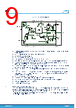
9 / 60 page  Figure 5. Internal block diagram RST DRIVER GND GND PEAK CL VALLEY CL ZERO CROSSING LOOP CONTROL OSCILLATOR RST TH. LX FB E/A POWER PMOS POWER NMOS SENSE PMOS SENSE NMOS Vcc SLOPE VIN SYNC COMP GND DRIVER GND GND VALLEY CL LOOP CONTROL E/A POWER PMOS MOS OVP + - MLF DELAY DELAY SS/INH SS/INH VREF 0 TSS + - FSW • Embedded power elements. Thanks to the P-channel MOSFET as high-side switch the device features low- dropout operation • A fully integrated sawtooth oscillator with adjustable frequency • A transconductance error amplifier • An internal feedback divider GDIV INT • The high-side current sense amplifier to sense the inductor current • A “Pulse Width Modulator” (PWM) comparator and the driving circuitry of the embedded power elements • The soft-start blocks to ramp the error amplifier reference voltage and so decreases the inrush current at power-up. The SS/INH pin inhibits the device when driven low • The switchover capability of the internal regulator to supply a portion of the quiescent current when the VBIAS pin is connected to an external output voltage • The synchronization circuitry to manage master / slave operation and the synchronization to an external clock • The current limitation circuit to implement the constant current protection, sensing pulse by pulse high-side / low-side switch current. In case of heavy short-circuit the current protection is fold back to decrease the stress of the external components • A circuit to implement the thermal protection function • The OVP circuitry to discharge the output capacitor in case of overvoltage event • MLF normally connected to GND through a resistor to set the threshold of the RST comparator • FSW pin strapping sets the switching frequency • The RST open collector output 4.1.1 Power supply and voltage reference The internal regulator block consists of a start-up circuit, the voltage pre-regulator that provides current to all the blocks and the bandgap voltage reference. The starter supplies the start-up current when the input voltage goes high and the device is enabled (SS/INH pin over the inhibits threshold). The pre-regulator block supplies the bandgap cell and the rest of the circuitry with a regulated voltage that has a very low supply voltage noise sensitivity. L6986I Primary side DS13647 - Rev 2 page 9/60 |
|
링크 URL |
| ALLDATASHEET 가 귀하에 도움이 되셨나요? [ DONATE ] |
Alldatasheet는? | 광고문의 | 운영자에게 연락하기 | 개인정보취급방침 | 링크 투 데이터시트 | 링크교환 | 제조사별 검색 All Rights Reserved©Alldatasheet.com |
| Russian : Alldatasheetru.com | Korean : Alldatasheet.co.kr | Spanish : Alldatasheet.es | French : Alldatasheet.fr | Italian : Alldatasheetit.com Portuguese : Alldatasheetpt.com | Polish : Alldatasheet.pl | Vietnamese : Alldatasheet.vn Indian : Alldatasheet.in | Mexican : Alldatasheet.com.mx | British : Alldatasheet.co.uk | New Zealand : Alldatasheet.co.nz |
|
Family Site : ic2ic.com |
icmetro.com |
 Korean ▼
 English
 Chinese
 German
 Japanese
 Russian
 Korean
 Spanish
 French
 Italian
 Portuguese
 Polish
 Vietnamese
 Indian
 Mexican
 British
 New Zealand