|
전자부품 데이터시트 검색엔진 |
|
|
전자부품 데이터시트 검색엔진 |
|
DSP56362AD 데이터시트(PDF) 20 Page - Motorola, Inc |
|
|
|||||||||||||||||||||||||||||
DSP56362AD 데이터시트(HTML) 20 Page - Motorola, Inc |
|
|
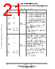
20 / 168 page  1-12 DSP56362 Advance Information MOTOROLA Signal/Connection Descriptions Host Interface (HDI08) HOST INTERFACE (HDI08) The HDI08 provides a fast, 8-bit, parallel data port that may be connected directly to the host bus. The HDI08 supports a variety of standard buses and can be directly connected to a number of industry standard microcomputers, microprocessors, DSPs, and DMA hardware. Host Port Configuration Signal functions associated with the HDI08 vary according to the interface operating mode as determined by the HDI08 port control register (HPCR). See 6.5.6 Host Port Control Register (HPCR) on page Section 6-13 for detailed descriptions of this register and (See Host Interface (HDI08) on page Section 6-1.) for descriptions of the other HDI08 configuration registers. RESET Input Input Reset—RESET is an active-low, Schmitt-trigger input. When asserted, the chip is placed in the reset state and the internal phase generator is reset. The Schmitt- trigger input allows a slowly rising input (such as a capacitor charging) to reset the chip reliably. If RESET is deasserted synchronous to CLKOUT, exact start-up timing is guaranteed, allowing multiple processors to start synchronously and operate together in “lock- step.” When the RESET signal is deasserted, the initial chip operating mode is latched from the MODA, MODB, MODC, and MODD inputs. The RESET signal must be asserted during power up. A stable EXTAL signal must be supplied while RESET is being asserted. This input is 5 V tolerant. Table 1-8 Interrupt and Mode Control (Continued) Signal Name Type State during Reset Signal Description Freescale Semiconductor, Inc. For More Information On This Product, Go to: www.freescale.com |
|
링크 URL |
| ALLDATASHEET 가 귀하에 도움이 되셨나요? [ DONATE ] |
Alldatasheet는? | 광고문의 | 운영자에게 연락하기 | 개인정보취급방침 | 링크 투 데이터시트 | 링크교환 | 제조사별 검색 All Rights Reserved©Alldatasheet.com |
| Russian : Alldatasheetru.com | Korean : Alldatasheet.co.kr | Spanish : Alldatasheet.es | French : Alldatasheet.fr | Italian : Alldatasheetit.com Portuguese : Alldatasheetpt.com | Polish : Alldatasheet.pl | Vietnamese : Alldatasheet.vn Indian : Alldatasheet.in | Mexican : Alldatasheet.com.mx | British : Alldatasheet.co.uk | New Zealand : Alldatasheet.co.nz |
|
Family Site : ic2ic.com |
icmetro.com |
 Korean ▼
 English
 Chinese
 German
 Japanese
 Russian
 Korean
 Spanish
 French
 Italian
 Portuguese
 Polish
 Vietnamese
 Indian
 Mexican
 British
 New Zealand