|
전자부품 데이터시트 검색엔진 |
|
|
전자부품 데이터시트 검색엔진 |
|
DSP56367 데이터시트(PDF) 9 Page - Freescale Semiconductor, Inc |
|
|
|||||||||||||||||||||||||||||
DSP56367 데이터시트(HTML) 9 Page - Freescale Semiconductor, Inc |
|
|
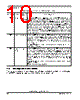
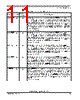
9 / 100 page  External Data Bus DSP56367 Technical Data, Rev. 2.1 Freescale Semiconductor 2-5 2.7 External Data Bus 2.8 External Bus Control Table 2-6 External Data Bus Signals Signal Name Type State during Reset Signal Description D0–D23 Input/Output Tri-Stated Data Bus—When the DSP is the bus master, D0–D23 are active-high, bidirectional input/outputs that provide the bidirectional data bus for external program and data memory accesses. Otherwise, D0–D23 are tri-stated. Table 2-7 External Bus Control Signals Signal Name Type State During Reset Signal Description AA0–AA2/ RAS0–RAS2 Output Tri-Stated Address Attribute or Row Address Strobe—When defined as AA, these signals can be used as chip selects or additional address lines. When defined as RAS, these signals can be used as RAS for DRAM interface. These signals are tri-statable outputs with programmable polarity. CAS Output Tri-Stated Column Address Strobe— When the DSP is the bus master, CAS is an active-low output used by DRAM to strobe the column address. Otherwise, if the bus mastership enable (BME) bit in the DRAM control register is cleared, the signal is tri-stated. RD Output Tri-Stated Read Enable—When the DSP is the bus master, RD is an active-low output that is asserted to read external memory on the data bus (D0-D23). Otherwise, RD is tri-stated. WR Output Tri-Stated Write Enable—When the DSP is the bus master, WR is an active-low output that is asserted to write external memory on the data bus (D0-D23). Otherwise, WR is tri-stated. TA Input Ignored Input Transfer Acknowledge—If the DSP is the bus master and there is no external bus activity, or the DSP is not the bus master, the TA input is ignored. The TA input is a data transfer acknowledge (DTACK) function that can extend an external bus cycle indefinitely. Any number of wait states (1, 2. . .infinity) may be added to the wait states inserted by the BCR by keeping TA deasserted. In typical operation, TA is deasserted at the start of a bus cycle, is asserted to enable completion of the bus cycle, and is deasserted before the next bus cycle. The current bus cycle completes one clock period after TA is asserted synchronous to the internal system clock. The number of wait states is determined by the TA input or by the bus control register (BCR), whichever is longer. The BCR can be used to set the minimum number of wait states in external bus cycles. In order to use the TA functionality, the BCR must be programmed to at least one wait state. A zero wait state access cannot be extended by TA deassertion, otherwise improper operation may result. TA can operate synchronously or asynchronously, depending on the setting of the TAS bit in the operating mode register (OMR). TA functionality may not be used while performing DRAM type accesses, otherwise improper operation may result. |
|
링크 URL |
| ALLDATASHEET 가 귀하에 도움이 되셨나요? [ DONATE ] |
Alldatasheet는? | 광고문의 | 운영자에게 연락하기 | 개인정보취급방침 | 링크 투 데이터시트 | 링크교환 | 제조사별 검색 All Rights Reserved©Alldatasheet.com |
| Russian : Alldatasheetru.com | Korean : Alldatasheet.co.kr | Spanish : Alldatasheet.es | French : Alldatasheet.fr | Italian : Alldatasheetit.com Portuguese : Alldatasheetpt.com | Polish : Alldatasheet.pl | Vietnamese : Alldatasheet.vn Indian : Alldatasheet.in | Mexican : Alldatasheet.com.mx | British : Alldatasheet.co.uk | New Zealand : Alldatasheet.co.nz |
|
Family Site : ic2ic.com |
icmetro.com |
 Korean ▼
 English
 Chinese
 German
 Japanese
 Russian
 Korean
 Spanish
 French
 Italian
 Portuguese
 Polish
 Vietnamese
 Indian
 Mexican
 British
 New Zealand