|
전자부품 데이터시트 검색엔진 |
|
|
전자부품 데이터시트 검색엔진 |
|
DSP56367 데이터시트(PDF) 13 Page - Freescale Semiconductor, Inc |
|
|
|||||||||||||||||||||||||||||
DSP56367 데이터시트(HTML) 13 Page - Freescale Semiconductor, Inc |
|
|
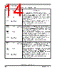
13 / 100 page  Parallel Host Interface (HDI08) DSP56367 Technical Data, Rev. 2.1 Freescale Semiconductor 2-9 HA2 HA9 PB10 Input Input Input, Output, or Disconnected GPIO Disconnected Host Address Input 2—When the HDI08 is programmed to interface a non-multiplexed host bus and the HI function is selected, this signal is line 2 of the host address (HA2) input bus. Host Address 9—When HDI08 is programmed to interface a multiplexed host bus and the HI function is selected, this signal is line 9 of the host address (HA9) input bus. Port B 10—When the HDI08 is configured as GPIO, this signal is individually programmed as input, output, or internally disconnected. The default state after reset for this signal is GPIO disconnected. This input is 3.3V tolerant. HRW HRD/ HRD PB11 Input Input Input, Output, or Disconnected GPIO Disconnected Host Read/Write—When HDI08 is programmed to interface a single-data-strobe host bus and the HI function is selected, this signal is the Host Read/Write (HRW) input. Host Read Data—When HDI08 is programmed to interface a double-data-strobe host bus and the HI function is selected, this signal is the host read data strobe (HRD) Schmitt-trigger input. The polarity of the data strobe is programmable, but is configured as active-low (HRD) after reset. Port B 11—When the HDI08 is configured as GPIO, this signal is individually programmed as input, output, or internally disconnected. The default state after reset for this signal is GPIO disconnected. This input is 3.3V tolerant. HDS/ HDS HWR/ HWR PB12 Input Input Input, Output, or Disconnected GPIO Disconnected Host Data Strobe—When HDI08 is programmed to interface a single-data-strobe host bus and the HI function is selected, this signal is the host data strobe (HDS) Schmitt-trigger input. The polarity of the data strobe is programmable, but is configured as active-low (HDS) following reset. Host Write Data—When HDI08 is programmed to interface a double-data-strobe host bus and the HI function is selected, this signal is the host write data strobe (HWR) Schmitt-trigger input. The polarity of the data strobe is programmable, but is configured as active-low (HWR) following reset. Port B 12—When the HDI08 is configured as GPIO, this signal is individually programmed as input, output, or internally disconnected. The default state after reset for this signal is GPIO disconnected. This input is 3.3V tolerant. Table 2-9 Host Interface (continued) Signal Name Type State During Reset Signal Description |
|
링크 URL |
| ALLDATASHEET 가 귀하에 도움이 되셨나요? [ DONATE ] |
Alldatasheet는? | 광고문의 | 운영자에게 연락하기 | 개인정보취급방침 | 링크 투 데이터시트 | 링크교환 | 제조사별 검색 All Rights Reserved©Alldatasheet.com |
| Russian : Alldatasheetru.com | Korean : Alldatasheet.co.kr | Spanish : Alldatasheet.es | French : Alldatasheet.fr | Italian : Alldatasheetit.com Portuguese : Alldatasheetpt.com | Polish : Alldatasheet.pl | Vietnamese : Alldatasheet.vn Indian : Alldatasheet.in | Mexican : Alldatasheet.com.mx | British : Alldatasheet.co.uk | New Zealand : Alldatasheet.co.nz |
|
Family Site : ic2ic.com |
icmetro.com |
 Korean ▼
 English
 Chinese
 German
 Japanese
 Russian
 Korean
 Spanish
 French
 Italian
 Portuguese
 Polish
 Vietnamese
 Indian
 Mexican
 British
 New Zealand